background image

38

Schaeffler Technologies


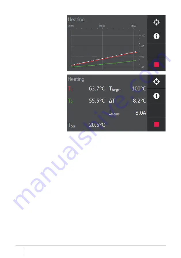
Unless the thermostat function is switched on, heating will 

stop automatically when the set temperature is reached. 

A loud beep sounds, and the display shows information 

about how the heating process went. The beep can be 

ended by pressing “

STOP

”.


When the thermostat function is switched on, unless 

you press “

STOP

”, the workpiece will be kept at the set 

temperature for the time set. Heating starts again after the 

temperature has dropped to the temperature set in the 

system settings to which the workpiece is allowed to drop. 

Each time the set temperature is reached, the induction 

heater sounds a loud beep.


During this cycle, a clock is displayed at the bottom of the 

screen with the time remaining for the temperature hold 

mode. After the temperature hold time has elapsed, the 

heater sounds a continued loud beep, which can be ended 

by pressing “

STOP

”.


Each time the induction heater stops, it automatically 

demagnetises the workpiece.


The heating process or thermostat feature can be interrupted 

by pressing the “

STOP

” button.

Summary of Contents for HEATER100-SMART

Page 1: ...Induction Heaters SMART Series User manual...

Page 2: ...empresa de transporte Debido a que nuestros productos est n continuamente sujetos a mejoras nos reservamos el derecho de realizar cambios Lisez le mode d emploi et les consignes de s curit avant la m...

Page 3: ...y the touch sensitive screen is oil resistant dustproof and waterproof When heating by induction is used there is no need at all to use oil this gives particularly good environmental compatibility The...

Page 4: ...ting elements 16 6 System settings 18 6 1 General 18 6 2 Explanation of system settings screen 1 19 6 3 Explanation of system settings screen 2 19 6 4 Explanation of system settings screen 3 20 6 5 Ex...

Page 5: ...8 11 2 Hold functionality 48 11 3 T functionality 51 11 4Target functionality 53 12 Cleaning maintenance and troubleshooting 54 13 Technical specifications 56 13 1Technical specifications HEATER50 200...

Page 6: ...n be developed further and an update is possible free of charge Changes to the software can lead to adjustments in the user manual A current version and translations of this user manual can be found a...

Page 7: ...n Forbidden for persons with metal implants Forbidden for magnetically sensitive data media Read the user manual Wear heat resistant gloves Wear safety shoes Warning of danger Electric shock hazard Wa...

Page 8: ...1 metre from the unit after switching on These fields can be harmful for persons with active medical aids such as pacemakers These fields can be harmful for persons with passive medical aids such as...

Page 9: ...ripping Caution Risk of burns The workpiece becomes warm to very hot during heating Parts of the unit may also become hot due to contact with the workpiece or the heat radiated by the workpiece Theref...

Page 10: ...ledge or component Never use a metal strap to support workpieces or suspend them in the magnetic field High currents could start running through the strap causing it to heat up Do not hold metal objec...

Page 11: ...oning cam An induction heater operates by means of a magnetic field At a distance of 1 metre the magnetic field has been reduced to such an extent that it is below the applicable standard of 0 5mT 2 4...

Page 12: ...ating cycle Bearings and workpieces can be heated to a maximum temperature of 240 C 464 F Schaeffler induction heaters are suitable for continuous use However when heating to a temperature of 240 C 46...

Page 13: ...nst the rating plate on the unit Each heater is equipped with a plug As there is a wide variety of plug types the attached plug may not fit In such cases obtain a proper plug It must be fitted by a qu...

Page 14: ...mperature sensor by inserting the plug into the socket Make sure that the and of the plug correspond to that of the socket The induction heater is now ready for use Ensure that the power supply cable...

Page 15: ...l measurement that can be used to monitor and adjust a temperature difference T in a workpiece during heating USB port for logging purposes stored heating data 5 Explanation of display buttons and con...

Page 16: ...t frequently used buttons and how variables can be set are explained below Start heating process Stop heating process To settings menu To administrator factory settings Not accessible to the end user...

Page 17: ...ders on off The corresponding option is switched on or off Slider not available The corresponding option cannot be switched on or off due to settings made elsewhere Variables can be set or changed by...

Page 18: ...rer in the Admin settings These settings are essential for the type of heater and are not at the user level and are therefore not accessible These settings are protected by a password The heater offer...

Page 19: ...which it returns if Default is pressed Default temp Setpoint temperature at which the heater starts or to which it returns if Default is pressed Default time Setpoint time with which the heater start...

Page 20: ...1 Offset Temperature probe 2 Calibration correction readout thermocouple 2 Unit Setting of the temperature measurement in C or F Language Setting of the language in which the texts on the screen are...

Page 21: ...planation of system settings screen 4 Min speed alarm Alarm if insufficient temperature increase is measured according to the Min speed limit setting Min speed Minimum temperature gradient T hold hyst...

Page 22: ...re difference between 2 measuring points on a workpiece at which the heating process is allowed to be switched on again after previously being switched off due to exceeding of the limit value for T T...

Page 23: ...sensor T1 on a flat area as close as possible to the bore Connect the sensor by inserting the plug into the socket in the casing Make sure that the and of the plug correspond to that of the socket If...

Page 24: ...t with the workpiece to be heated Damage to the cable can cause electrocution Never use a metal strap to support workpieces or suspend them in the magnetic field High currents could start running thro...

Page 25: ...t the heat stays in the workpiece and does not dissipate A workpiece can be placed in different ways Hanging with ledge through the workpiece Horizontal with workpiece around the pole Hanging with led...

Page 26: ...se order Use heat resistant gloves to move the heated workpiece Make sure that the bare metal sides are sufficiently coated with grease to ensure optimal contact and avoid vibration Swivel arm models...

Page 27: ...stant gloves to move the heated workpiece 8 3 Maximum weights for swivel arm models Keep to these maximum weights and avoid tilting the heater or damaging the supports swivel ledges or hinge Type On s...

Page 28: ...ries with the time mode In the event of an emergency If the sensor is faulty as a contingency measure the workpiece can be heated with the time mode The temperature may be measured with an external th...

Page 29: ...ing the current mode on the settings screen A selection menu appears below the current mode in which one of the four heating modes can be selected by tapping The selection made is then displayed under...

Page 30: ...given workpiece to a given temperature This is the only mode in which the heater can function without temperature sensors being connected Time or Temperature mode Heating of workpieces to a set temper...

Page 31: ...ter switching on the process the heater controls the power output so the heating curve for the workpiece follows the gradient set During heating a white dotted line is shown in the chart indicating th...

Page 32: ...e temperature set by pressing the current temperature If desired switch on the hold temp thermostat mode and log functionality by moving the sliders to the right These will now turn green Press START...

Page 33: ...kpiece will be kept at the set temperature for the time set Heating starts again after the temperature has dropped to the temperature set in the system settings to which the workpiece is allowed to dr...

Page 34: ...s START The heating starts you will hear a slight humming sound The display shows the time left until process completion 9 3 Heating in time mode If you have connected the sensors and placed them on t...

Page 35: ...on heater switches off The workpiece is then demagnetized automatically and a loud continuous beep sounds Press STOP to switch off the beep 9 4 Heating in temperature or time mode Position the workpie...

Page 36: ...rent values Press START The heating starts you will hear a slight humming sound The display shows the temperature and the time left until process completion By pressing the info button the heating pro...

Page 37: ...r and select the temperature speed mode if necessary If necessary change the temperature and gradient set by pressing the current values Press START The heating starts you will hear a slight humming s...

Page 38: ...ain after the temperature has dropped to the temperature set in the system settings to which the workpiece is allowed to drop Each time the set temperature is reached the induction heater sounds a lou...

Page 39: ...n switch the device on again Thermocouple 1 disconnected Thermocouple 1 is not connected or defective Connect a thermocouple or try a different thermocouple Thermocouple 2 disconnected Thermocouple 2...

Page 40: ...e current through the capacitor is too high Switch the device off and on and try again If the problem persists contact your supplier The coil temperature is too low The coil temperature 10 C Switch of...

Page 41: ...such as temperature time power operator and workpiece data NOTE In order to be able to log and export these data an empty USB data carrier not supplied must be plugged in to the USB port provided at t...

Page 42: ...corresponding field Repeat the above steps if necessary for the other input field Pressing START now starts the heating process and the heating data are coupled to the entered data operator and projec...

Page 43: ...firm the message and to clear the message from the screen The file is now stored as a CSV file comma separated variables that can be imported for example into Microsoft Excel for processing as a repor...

Page 44: ...ogs data on stored heating processes Alarms occurring during the process Press the Log button on the right side of the settings screen to view the logs An overview screen is displayed with three types...

Page 45: ...eating data from shortly before the generator crashed failed In the overview tap Last crash The data from shortly before the crash is displayed If a USB data carrier is connected the heating data can...

Page 46: ...memory View Pressing View after selecting a file displays the heating information of the process Pressing the Heating logs button displays a list of saved heating logs If a USB data carrier is connect...

Page 47: ...selecting a log file the file may be deleted A confirmation screen appears If you press NO you return to the list of log files If you press YES a confirmation screen appears confirming that the file h...

Page 48: ...s a slider with which the temperature hold functionality Temp Hold can be switched on or off This functionality enables a workpiece to be held at a set temperature once that temperature has been reach...

Page 49: ...iece is heated to 80 C and then kept at 80 C for 2 minutes When the Hold Temp functionality is activated the slider turns green and the hold temp duration of the workpiece is displayed By pressing Hol...

Page 50: ...appear at the bottom of the screen indicating the remaining time the workpiece is kept at the set temperature As soon as this time has elapsed the heater displays a message indicating that the temp ho...

Page 51: ...ater and positioned correctly on the workpiece Positioning of sensors Position sensor T1 red at the point where the heat is applied to the workpiece this is usually the bore This sensor is the main se...

Page 52: ...ted manually If Auto restart is active the heating process will restart automatically as soon as the temperature difference is smaller than the temperature set under T switch on This must be achieved...

Page 53: ...4 Target functionality In all heating modes a target button is displayed in the top right hand corner during heating In this example heating in the temperature mode is used for illustration purposes P...

Page 54: ...surfaces clean and greased Is the ledge positioned level on the poles If this is not the case follow the instructions below to adjust the ledge Models with horizontal ledge 1 Remove dirt burrs etc fro...

Page 55: ...turer or a specialist approved by the manufacturer 3 5 4 Models with vertical ledge 1 Remove dirt burrs etc from the ledge and poles and grease lightly 2 Place the ledge in front of the poles 3 Loosen...

Page 56: ...Double T measurement Log functionality Operating modes Time Temperature Temperature or time Temperature speed Weight kg 21 31 52 56 Max temperature 240 C 464 F Max bearing weight kg 50 100 150 200 Ma...

Page 57: ...me Temperature Temperature or time Temperature speed Weight kg 150 170 250 720 Max temperature 240 C 464 F Max bearing weight kg 400 600 800 1600 Max OD mm A 850 1050 1150 1700 Space between poles mm...

Page 58: ...0V 230V 16A 3 7 CE HEATER150 SMART 240V US 240V 16A 3 8 QPS HEATER200 SMART 400V 2 400V 20A 8 CE HEATER200 SMART 450V 2 450V 16A 7 2 CE HEATER200 SMART 500V 2 500V 16A 7 7 CE HEATER200 SMART 480V US 2...

Page 59: ...ATER800 SMART 400V 400V 60A 24 CE HEATER800 SMART 450V 450V 50A 24 CE HEATER800 SMART 500V 500V 48A 24 CE HEATER800 SMART 480V US 480V 48A 24 QPS HEATER800 SMART 600V US 600V 40A 24 QPS HEATER1600 SMA...

Page 60: ...280 0 40 Yes HEATER100 YOKE 30 30 20x20x280 0 84 Yes HEATER100 YOKE 45 45 30x30x280 2 40 Yes HEATER100 YOKE 60 60 40x40x280 3 87 Yes HEATER100 YOKE 68 72 50x50x280 5 78 Yes HEATER100 YOKE 85 85 60x60x...

Page 61: ...130 130 90x90x600 37 90 Yes HEATER800 SMART Name Min bore diam mm Size mm Weight kg Swivel arm Scope of delivery Optional HEATER800 YOKE 60 60 40x40x725 9 00 No HEATER800 YOKE 72 72 50x50x725 14 5 No...

Page 62: ...he device or damage to workpieces and any consequential damage resulting from a defect in the device Power tools accessories and packaging must be reused at the end of their life cycle in an environme...

Page 63: ...T 230V HEATER100 SMART 120V HEATER100 SMART 230V HEATER150 SMART 230V HEATER200 SMART 400V HEATER200 SMART 450V HEATER200 SMART 500V HEATER400 SMART 400V HEATER400 SMART 450V HEATER400 SMART 500V HEAT...

Page 64: ...piled and checked by us but we cannot guarantee complete accuracy We reserve the right to make corrections Therefore please always check whether more up to date or amended information is available Thi...

Reviews: