background image


15


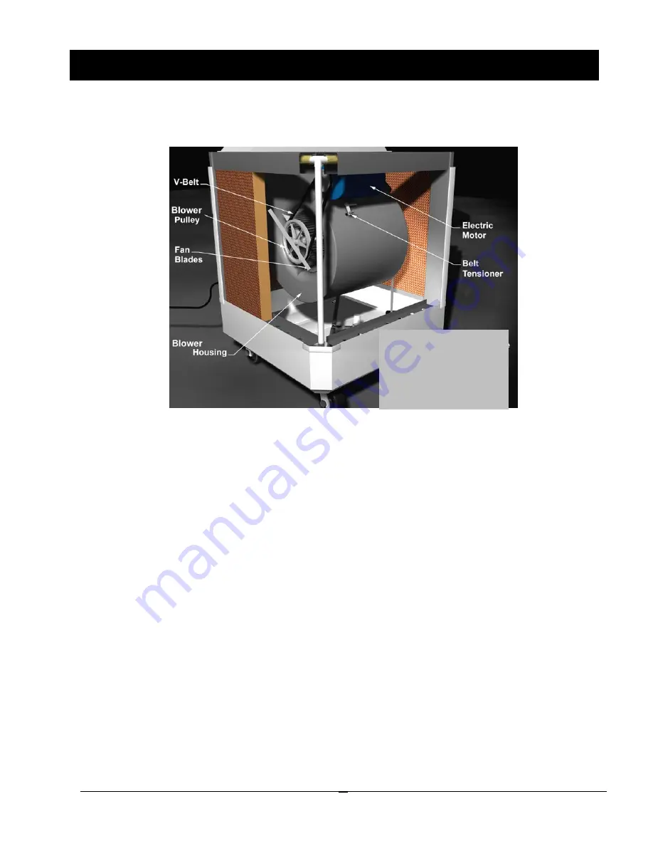
Figure WC-1HP-DHL.07 - Fan Blower 


The WayCool

®

 WC-1HP-DHL uses a belt-driven, 1 HP electric motor to drive a centrifugal blower. The blower 

draws room air through the cooling pads and discharges the cooler air through the blower duct, displacing the 
warmer air with cooler air and decreasing the temperature. 
 
The blower is secured to the top of the frame and hangs upside down to direct the air out the top of the unit. 
Brackets on each side of the blower casing secure the blower to the frame and hold it in position. 
 
The electric motor is bolted to a metal bracket on the blower casing. A V-belt connects the pulley on the motor 
shaft to the larger pulley on the blower shaft. Both shafts have sealed roller bearings, which do not require 
lubrication. 

Blower and Ductwork 

A belt tensioner is connected to a bracket on the motor. A rubber foot at one end rests against the blower 
casing. When the locking nut is backed off, the bolt can be turned in to tighten the V-belt or backed out to 
loosen or remove the V-belt. 
 

Note: Do not over tighten the V-belt as you can prematurely wear out the bearings. 
 

The power cord runs down the frame leg that has the control switch on the outside. It exits the frame leg at the 
bottom and has a male plug that must be plugged into a suitable hazardous location receptacle. The cord is 
approximately fifteen feet long. 
 

Note: The WC-1HP-DHL unit requires 120 volts and 20 amps of power. This is normally available on 
most circuits. However, if you are running a number of other items on the same circuit, you may trip 
the breaker.


Blower and 
 D 

BLOWER AND DUCTWORK

Actual WC-1HP-DHL 
WayCool® varies 
slightly from unit shown 

here. 

Summary of Contents for Waycool WC-1HP-DHL

Page 1: ...Division 2 Not normally present in an explosive concentration but may accidentally exist Testing Certifications Standards Electrical Equipment for Use in Class I and Class II Division 2 and Class III...

Page 2: ...11 WATER SUPPLY SYSTEM 11 COOLING PAD ASSEMBLY 14 BLOWER AND DUCTWORK 15 CONTROL 16 OPERATION AND MAINTENANCE 17 Unit Placement and Other Considerations 17 Unpacking and Initial Setup 18 Regular Clea...

Page 3: ...ign and construction of the cooling pads cooling efficiency is normally maintained near optimum throughout the life of the pads which can easily last for about two seasons with proper care In many cas...

Page 4: ...n from the pads and the air dropping the air temperature and producing the cooling effect The cooled air is then forced through a building or space and displaces the warm air out building openings coo...

Page 5: ...e and questions regarding your product Important Read ALL instructions carefully before starting your WayCool Important Pay particular attention to all SAFETY information All information illustrations...

Page 6: ...his is a safety alert symbol When you see this symbol on your equipment be alert to the potential for personal injury This equipment is designed to be installed and operated as safely as possible howe...

Page 7: ...s prolongs the life of the pads CLEANING Clean pads a minimum of once every CAUTION ALWAYS TURN OFF AT SWITCH AND DIS two weeks Remove pads from unit CONNECT POWER BEFORE REMOVING EVAPORA and clean wi...

Page 8: ...njured by the rotating fan blades Do not service the electrical components unless you are certified to do so The metal frame edges are sharp don t run your hand along them Be careful and wear gloves w...

Page 9: ...Filter Washable Polyethylene Filter Pump Discharge Filter 480 Micron Stainless Steel Reservoir Capacity 24 Gallons Optional Water Supply Standard hose connection garden hose size Housing High impact A...

Page 10: ...lly enclose the unit The blower is hung from the top of the frame and powered by a belt driven 1HP electric motor The blower draws room air through the cooling pads where it picks up moisture and cool...

Page 11: ...ose or bucket if a hose connection is impractical Simply remove any of the plastic retaining grates and one of the cooling pad sections and place the hose or pour the water directly into the bottom Wh...

Page 12: ...y removed for inspection or cleaning Water Supply System The pump sits on a foam filter somewhat like a sponge The filter traps dirt that could enter the water distribution system and build up on the...

Page 13: ...the water as it leaves the spray holes This gives a more even water distribution across the cooling pad and reduces splashing The holes direct the water inward at a 90 angle to continuously saturate...

Page 14: ...with the plastic retaining grates in place and handle them carefully when you clean them Crushed cells reduce the total airflow through the unit and therefore lowers it s cooling capacity The cooling...

Page 15: ...o not require lubrication Blower and Ductwork A belt tensioner is connected to a bracket on the motor A rubber foot at one end rests against the blower casing When the locking nut is backed off the bo...

Page 16: ...trol Switch Both the manual Motor starter switch and the Pump switch function as ON OFF only The unit can run with pump only ON fan motor only ON or both ON CONTROLS Manual Motor starter switch ON OFF...

Page 17: ...t of the building Try to get all the air flowing in the same direction Do not direct other fans against the WayCool unit It will counter the WayCool s airflow and stop the cooling effect Obstructing t...

Page 18: ...tic retaining grates from all four sides of the unit Use your fingers to lift each upward then outward from the bottom 5 Remove the cooling pads from all four sides of the unit Place a putty knife or...

Page 19: ...r cleaning let the pads air dry before you replace them 1 Turn the switch to OFF and unplug the unit 2 Remove the grate brackets and the plastic retaining grates and check the pads for cleanliness If...

Page 20: ...spill damage 7 Plug the unit into an outlet 8 Adjust the blower duct to discharge the cool air in the desired direction and tighten the knob on the end of the threaded rod 9 Turn the pump switch to t...

Page 21: ...of the water and the amount of dirt dust etc in the supply air you may have to clean the PVC pipes from time to time Your own experience will dictate the frequency 1 Turn off the unit and unplug it 2...

Page 22: ...t Front See Line Clogs or Obstructions LEAKING Out Bottom Check for cracks on the bottom If a crack is found a new bottom will have to be ordered See Ordering Replacement Parts page 24 Troubleshooting...

Page 23: ...should arise your Schaefer dealer can supply the necessary information to help you Dealer Product Information ORDERING REPLACEMENT PARTS To order replacement parts contact the dealer from whom you pu...

Page 24: ...above constitutes our sole warranty THERE IS NO WARRANTY OF MERCHANTABILITY AND THERE ARE NO WARRANTIES WHICH EXTEND BEYOND THE DESCRIPTION OF THE FACE HEREOF Products with warranty periods that exce...

Page 25: ...Schaefer Ventilation Equipment M WC1HPDHL 10 03...

Reviews: