background image

27


NOTE: If converting an existing machine, on which you want to mount the belt arm, 
you also need to order the adapter. 


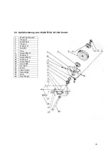
5.6. Mounting the belt arm 


If the grinder is mounted with a grinding guard, this must be removed completely before 
mounting the belt arm. When mounting the belt arm, you must install the adapter (H) first, 
and then you can mount the belt arm on the adapter, and you have to tighten it in place 
with the bolt (I). Then you can put the spacer (G) on the axis and then the contact wheel 
(F) and finally the nut (E). Then put the sanding belt (D) on the belt arm, and finally the belt 
cover (C) is mounted by flat washer (B) and nut (A).  


5.7. Changing the grinding belt 

When the grinding belt is worn, replace it, which is done as follows: Belt cover (A) (see 
Fig.: 3.2) on belt housing is removed and lever (B) is pulled down. This relieves the 
grinding belt (C) so that it can be removed and replaced with a new belt, which is mounted 
in the opposite order. Check that the direction of the arrows on the belt back corresponds 
to the direction of rotation. When the new grinding belt is mounted, it is necessary to adjust 
the straight with the handle (D), which is loosened until the grinding belt runs straight on 
the contact disc. Then tighten the lever (B). 

NOTE: This adjustment of the grinding belt should only be performed by pulling the 
grinding belt with your hands and not with the machine turned on. 


There are many different kinds of grinding belts, it is therefore important to choose the 
correct type. Consideration must be given to the material the item is made of, which may 
include varied in grain size, grinding belt material and glue. 

Also it’s important to know that 

47 

Mellemstykke 

Adapter 

1065374 

Summary of Contents for SC 150

Page 1: ...Industrivej 3 9 DK 9460 Brovst Tlf 45 98 23 60 88 Fax 45 98 23 61 44 DK MANUAL SCANTOOL SC 150 200 SLIBE POLÉRMASKINER GRINDERS POLISHERS SCHLEIF POLIERMASCHINEN ...

Page 2: ...ropa Parlamentets og Rådets direktiv 2006 42 EF af 17 maj 2006 Samt i overensstemmelse med Lavspænding EUROPA PARLAMENTETS OG RÅDETS DIREKTIV 2014 35 EU af 26 februar 2014 EMC EUROPA PARLAMENTETS OG RÅDETS DIREKTIV 2014 30 EU af 26 februar 2014 SCANTOOL A S Industrivej 3 9 9460 Brovst Danmark www scantool dk Tlf 45 98 23 60 88 Fax 45 98 23 61 44 ...

Page 3: ...3 Indholdsfortegnelse 1 FØR STRØMMEN TILSLUTTES 4 2 NÅR MASKINEN STARTES 4 3 SLIBERÅD 5 4 SIKKERHEDSREGLER FOR STATIONÆRE VÆRKTØJSMASKINER 6 5 TEKNISKE DATA 8 6 EL DIAGRAMMER 14 7 GARANTI 15 ...

Page 4: ...uttet el nettet 2 NÅR MASKINEN STARTES Start motoren og lad maskinen arbejde for fuld hastighed i min 30 sek For nye maskiner og efter udskiftning af slibeskiver tilrådes dog 5 min Ophold Dem ikke foran maskinen i dette tidsrum Før emnet roligt ind mod slibeskiven og undgå hårde stødvise tryk og hug Brug altid et let fast tryk Lad maskinen rotere med højeste hastighed Tænk på arbejdsstedets omgive...

Page 5: ... værktøjer skal anvendes Grove arbejder og hårdt materiale kræver større æg vinkel Nogle eksempler Knive ca 20 Høvlejern 25 Stemmejern hårdt materiale ca 30 blødt materiale ca 20 25 Under slibning dannes en rå æg som efter slibning fjernes med en fin hvæssesten Undgå overdrevet tryk på slibeskiven Det nedsætter hastigheden slibeevnen og skivens levetid ligesom motoren overbelastes Stands ikke skiv...

Page 6: ...er der er udstyret med kraftstik Hvis man bruger adapter til at tilpasse et 2 benet stik skal adapteren altid tilsluttes til en jordforbindelse Fjern aldrig det 3 ben 4 Fjern tilpasningsnøgler og skruenøgler Gør det til en vane at tjekke at disse er fjernet før maskinen tilsluttes 5 Hold arbejdsbordet rent Rod kan føre til uheld 6 Undgå farligt arbejdsmiljø Anvend ikke værktøjsmaskiner i fugtige e...

Page 7: ...ækkevidde Hav et godt fodfæste og en god balance hele tiden 15 Vedligehold værktøjet omhyggeligt Den bedste og sikreste udførsel opnås ved at holde værktøjet skarpt og rent Følg instruktionerne ved smøring og udskiftning af reservedele 18 Brug anbefalede reservedele Se efter anbefalede reservedele i manualen Ved at anvende ukurante reservedele kan mennesker komme til skade 17 Afbryd strømmen til v...

Page 8: ...8 5 TEKNISKE DATA 5 1 Splittegning af SCANTOOL SC 150 200 T E ...

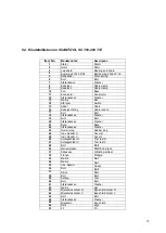
Page 9: ...t Bolt 18 Afstandsskive Washer 19 Bolt Bolt 20 Afstandsskive Washer 21 Bund Base 22 Afstandsskive Washer 23 Gummiprop Rubber plug 24 Indv Skærm H Cover R 25 Indv Skærm V Cover L 26 Anlægsholder H Tool rest R 27 Anlægsholder V Tool rest L 28 Bolt Bolt 29 Mellemstykke Distance piece 31 Slibeskive Grinding wheel 32 Flange Flange 33 Møtrik Nut 34 Møtrik Nut 35 Udv Skærm Cover 36 Bolt Bolt 37 Skive Dis...

Page 10: ...OL SC 200 Combi 1 Wet Wheel Guard 2 Flange II 3 Wet Wheel 4 Flange I 5 Washer 12 6 Nut M12 7 Plug 8 Screw M4x12 13 Washer 5 18 Screw M5x12 37 Washer 4 38 Screw M4x8 42 Cear shaft 43 Pin 5x25 44 Worm 45 Case Cover 46 Case Body 47 Gear 48 Axle Sleeve ...

Page 11: ...11 5 4 Splittegning af båndarm 50x800 ...

Page 12: ...x10 Screw M5x10 1538019 20 Drivhjul Drive wheel 1538020 22 Møtrik 18mm Hex nut 18mm 0932305 23 Slibeanlæg Wheel flange belt support plate 1538023 24 Fjeder Spring pin M4x16 1538024 25 Skive x 16 Flat washer x 16 1538025 26 Stjernegreb x 28mm Star knob x 28mm 1538026 27 Fjederskive Spring washer 1538027 28 Aksel m gevind Stud 1538028 29 Slibebånd 50x800 Belt 50x800 0214080 30 Topdæksel Upper cover ...

Page 13: ...es ned Herved aflastes slibebåndet C så det kan afmonteres og udskiftes med et nyt slibebånd som monteres i modsat række følge Det kontrolleres at pilenes retning på båndets bagside svarer til omløbsretningen Når det nye slibebånd er monteret er det nødvendigt at justere for ligeløb med håndtaget D som løsnes indtil slibebåndet løber lige på kontaktskiven Herefter tilspændes håndtaget B OBS Denne ...

Page 14: ...rdet det er også muligt at afmontere planslibebordet og derved slibe frit på slibebåndet Før emnet roligt ind mod slibebåndet og undgå hårde stødvise tryk eller hug brug altid et let fast tryk for at undgå at ødelægge slibebåndet og overbelaste motoren 6 EL DIAGRAMMER 6 1 Diagram 3x400V 6 2 Diagram 1x230V ...

Page 15: ...kke er blevet anvendt forkert eller mishandlet 3 Der ikke er forsøgt reparationsarbejde af andre personer end vort eget servicepersonale eller personale hos vore officielle serviceagenter 4 Fakturer kopi vedlægges når maskinen sendes til reparation 5 Sliddele indgår ikke under garantien SCANTOOL A S giver 5 års garanti på den elektriske motor hvis denne bliver defekt eller udbrændt inden for de fø...

Page 16: ...an Parliament and Council Directive 2006 42 EC of 17 May 2006 And also in accordance with Low Voltage EUROPEAN PARLIAMENT AND COUNCIL DIRECTIVE 2014 35 EU of 26 February 2014 EMC EUROPEAN PARLIAMENT AND COUNCIL DIRECTIVE 2014 30 EU of 26 February 2014 SCANTOOL A S Industrivej 3 9 9460 Brovst Denmark www scantool com Tel 45 98 23 60 88 Fax 45 98 23 61 44 ...

Page 17: ...17 Table of contents 1 INSTALLATION 18 2 WHEN STARTING AND OPERATING THE MACHINE 18 3 WHEEL CARE 19 4 SAFETY RULES FOR STATIONARY POWER TOOLS 20 5 TECHNICAL DATA 22 6 WIRING DIAMGRAMS 28 7 WARRANTY 29 ...

Page 18: ...ved freely by hand The tool rests are in position adjusted to within 3 mm 1 8 of the periphery face of the wheel and firmly secured The protective eye shields fitted to Bench Grinders are clean and secured in the correct position or that recommended and approved type of protective goggles with clean lenses are worn before operating the machine All adjustments and checks are made with the machine d...

Page 19: ...ls and the storage surface Similar material should be placed between wheels when a number are being stored As the grinding wheel is used it will wear it is recommended that the wheel is replaced when the diameter has been reduced approximately 25 below the original size e g 300 mm to 225 mm 200 mm to 150 mm 150 mm to 112 mm and 12 5 mm to 94 mm Wear on the wheel can cause eccentricity leading to m...

Page 20: ... this tool 2 Keep guard in place and in working order 3 Ground all tools If tool is equipped with three prong plug it should be plugged into a three hole electrical receptacle If an adapter is used to accommodate a two prong receptacle the adapter wire must be attached to a known ground Never remove the third prong 4 Remove adjusting keys and wrenches Form habit of checking to see that keys and ad...

Page 21: ... have impact resistant lenses They are NOT safety glasses 13 Secure works Use clamps or vise to hold works when practical It s safer than using your hands and it frees both hands to operate tool 14 Don t overreach Keep proper footing and balance at all times 15 Maintain tools with care Keep tools sharp and clean for best and safest performance Follow instructions for lubricating and changing acces...

Page 22: ...22 5 TECHNICAL DATA 5 1 Drawing of SCANTOOL SC 150 200 T E ...

Page 23: ... Bolt 18 Afstandsskive Washer 19 Bolt Bolt 20 Afstandsskive Washer 21 Bund Base 22 Afstandsskive Washer 23 Gummiprop Rubber plug 24 Indv Skærm H Cover R 25 Indv Skærm V Cover L 26 Anlægsholder H Tool rest R 27 Anlægsholder V Tool rest L 28 Bolt Bolt 29 Mellemstykke Distance piece 31 Slibeskive Grinding wheel 32 Flange Flange 33 Møtrik Nut 34 Møtrik Nut 35 Udv Skærm Cover 36 Bolt Bolt 37 Skive Disc...

Page 24: ... SC 200 Combi 1 Wet Wheel Guard 2 Flange II 3 Wet Wheel 4 Flange I 5 Washer 12 6 Nut M12 7 Plug 8 Screw M4x12 13 Washer 5 18 Screw M5x12 37 Washer 4 38 Screw M4x8 42 Cear shaft 43 Pin 5x25 44 Worm 45 Case Cover 46 Case Body 47 Gear 48 Axle Sleeve ...

Page 25: ...25 5 4 Drawing of belt arm 50x800 ...

Page 26: ...ve wheel 1538020 22 Møtrik 18mm Hex nut 18mm 0932305 23 Slibeanlæg Wheel flange belt support plate 1538023 24 Fjeder Spring pin M4x16 1538024 25 Skive x 16 Flat washer x 16 1538025 26 Stjernegreb x 28mm Star knob x 28mm 1538026 27 Fjederskive Spring washer 1538027 28 Aksel m gevind Stud 1538028 29 Slibebånd 50x800 Belt 50x800 0214080 30 Topdæksel Upper cover belt 1538030 31 Slibeanlæg Tool rest up...

Page 27: ...see Fig 3 2 on belt housing is removed and lever B is pulled down This relieves the grinding belt C so that it can be removed and replaced with a new belt which is mounted in the opposite order Check that the direction of the arrows on the belt back corresponds to the direction of rotation When the new grinding belt is mounted it is necessary to adjust the straight with the handle D which is loose...

Page 28: ...act wheel or on the surface grinding table it is also possible to remove surface grinding table and thereby grind freely on the grinding belt Lead the issue calmly toward the grinding belt and avoid harsh jerky pressure or blows always use a light firm pressure to avoid destroying the grinding belt and overloading the engine 6 WIRING DIAGRAMS 6 1 Diagram 3x400V 6 2 Diagram 1x230V ...

Page 29: ...ot been misused or carelessly handled and in particular has not been used in a manner contrary to the operating instructions 3 Repairs have not been made or attempted by other than our own Service Staff or the staff of our Official Service Agents 4 Documentary proof of purchase date is produced when the goods are handed in or sent for repair 5 Wear parts are not covered by the warranty Scan tool A...

Page 30: ... Parlaments und des Rates Richtlinie 2006 42 EG des Rates vom 17 Mai 2006 sowie gemäß Niederspannung EUROPÄISCHE PARLAMENT UND DER RICHTLINIE 2014 35 EU vom 26 Februar 2014 EMC EUROPÄISCHE PARLAMENT UND DER RICHTLINIE 2014 30 EU vom 26 Februar 2014 SCANTOOL A S Industrivej 3 9 9460 Brovst Dänemark www scantool de Tel 45 98 23 60 88 Fax 45 98 23 61 44 ...

Page 31: ...tverzeichnis 1 INSTALLATION 32 2 INTRIEBNAHME DER SCHLEIFMASCHINE 32 3 SCHLEIFANWEISUNGEN 33 4 SICHERHEITSREGELN FÜR STATIONÄRE MASCHINENWERKZEUGE 34 5 TEKNISCHE DATA 36 6 ELEKTRISCHE DIAGRAMME 42 7 GARANTIE 43 ...

Page 32: ...ntfernt ist Nehmen Sie Justierungen und Kontrollen nur bei abgeschalteter Maschine vor Beim Schleifen ist eine geeignete Schutzbrille zu tragen Stets die entsprechenden Unfallverhütungsvorschriften bitte beachten In Zweifelsfällen den technischen Aufsichtsbeamten befragen 2 INBETRIEBNAHME DER SCHLEIFMASCHINE Schalten Sie die Schleifmaschine ein und lassen Sie sie mindestens 30 Sekunden mit voller ...

Page 33: ...Sie die Maschine nach dem Abschalten frei auslaufen Die Maschine soll max 30 Min je Stunde arbeiten 3 1 Schleifscheiben Es gibt drei verschiedene Schleifscheibentypen für Ihre Schleifmaschine Normal Korund Für gewöhnliche Schleifarbeit von Handwerkzeug Gartengeraten z B Spiralbohren Meißeln Messern Schraubenziehern Äxten Beilen Heckenscheren Messern für Rotorrasenmäher Edel Korund Für das Schleife...

Page 34: ... richtig positioniert sind und sich in einem guten Zustand befinden 3 Alle Werkzeugmaschinen mit eigenem Stromanschluss müssen eine eigene Erdverbindung haben Wenn man einen Adapter für die Anpassung eines 2 poligen An Schlusses verwendet muss der Adapter immer eine Erdung haben Entfernen Sie niemals den 3 Stift 4 Entfernen Sie die Schlüssel zur Anpassung und die Schrauben schlüssel Machen Sie sic...

Page 35: ... 14 Kenne deine Reichweite Sorgen Sie die ganze Zeit für guten Halt und Gleich gewichte 15 Pflegen Sie das Werkzeug sorgfältig Die Arbeit lässt sich am Besten mit sauberen und scharfen Werkzeugen verrichten Befolgen Sie die Anweisungen zur Schmierung und Austausch von Ersatzteilen 16 Minimieren Sie die Gefahr eines unbeabsichtigten Anlaufens der Maschine Vergewissern Sie sich dass der Schalter aus...

Page 36: ...36 5 TECHNISCHE DATA 5 1 Split Zeichnung vom SCANTOOL SC 150 200 T E ...

Page 37: ...t Bolt 18 Afstandsskive Washer 19 Bolt Bolt 20 Afstandsskive Washer 21 Bund Base 22 Afstandsskive Washer 23 Gummiprop Rubber plug 24 Indv Skærm H Cover R 25 Indv Skærm V Cover L 26 Anlægsholder H Tool rest R 27 Anlægsholder V Tool rest L 28 Bolt Bolt 29 Mellemstykke Distance piece 31 Slibeskive Grinding wheel 32 Flange Flange 33 Møtrik Nut 34 Møtrik Nut 35 Udv Skærm Cover 36 Bolt Bolt 37 Skive Dis...

Page 38: ...00 Combi 1 Wet Wheel Guard 2 Flange II 3 Wet Wheel 4 Flange I 5 Washer 12 6 Nut M12 7 Plug 8 Screw M4x12 13 Washer 5 18 Screw M5x12 37 Washer 4 38 Screw M4x8 42 Cear shaft 43 Pin 5x25 44 Worm 45 Case Cover 46 Case Body 47 Gear 48 Axle Sleeve ...

Page 39: ...39 5 4 Split Zeichnung vom Bandschleifvorrichtung 50x800 ...

Page 40: ...ul Drive wheel 1538020 22 Møtrik 18mm Hex nut 18mm 0932305 23 Slibeanlæg Wheel flange belt support plate 1538023 24 Fjeder Spring pin M4x16 1538024 25 Skive x 16 Flat washer x 16 1538025 26 Stjernegreb x 28mm Star knob x 28mm 1538026 27 Fjederskive Spring washer 1538027 28 Aksel m gevind Stud 1538028 29 Slibebånd 50x800 Belt 50x800 0214080 30 Topdæksel Upper cover belt 1538030 31 Slibeanlæg Tool r...

Page 41: ...Wenn das Schleifband verschlissen ist ersetzen Sie sie was geschieht wie folgt äußeren Schirm A siehe Ab 3 2 wird auf Box entfernen und Hebel B nach unten gezogen Dies entlastet den Schleifband C so dass sie entfernt und ersetzt werden mit einem neue Schleifband die in dem entgegengesetzten Ergebnis angebracht ist Prüfen ob die Richtung der Pfeile auf dem Band zurück entspricht der Richtung der Dr...

Page 42: ...chleifen kann durch Kontaktscheibe vorgenommen werden oder auf Planschleiftisch Es ist auch möglich Planschleiftisch zu entfernen und dadurch frei auf Schleifband schleifen Führen Sie das Material ruhig in Richtung des Schleifbands und vermeiden Sie ruckartige harten Druck oder Schläge sollten Sie immer einen leichten festen Druck nicht das Schleifband zu zerstören und eine Überlastung des Motors ...

Page 43: ...paratur oder kostenlosen Ersatz defekter Teile wenn Die Maschine komplett an eine unserer Kundendienstabteilungen zurückgesandt wird Die Maschine nicht unsachgemäß verwandt worden ist Die Reparaturarbeit von unserem eigenen Kundendienstpersonal oder dem Personal unserer Kundendienstvertretungen ausgeführt wird Die Rechnung mit dem Datum des Kaufs oder der Garantieschein der Rucksendung beigefugt i...

Reviews: