background image

27

R

Section 6

CUTTER DECk HEIGHT

The cutter deck height adjustment is made to insure that the 
cutter deck is cutting at the height indicated on the cutting 
height index gauge. To check for proper deck height, be 
sure that the mower is on a flat, level surface and the tires 
are properly inflated.

Place the cutter deck in the transport position. 

1. 

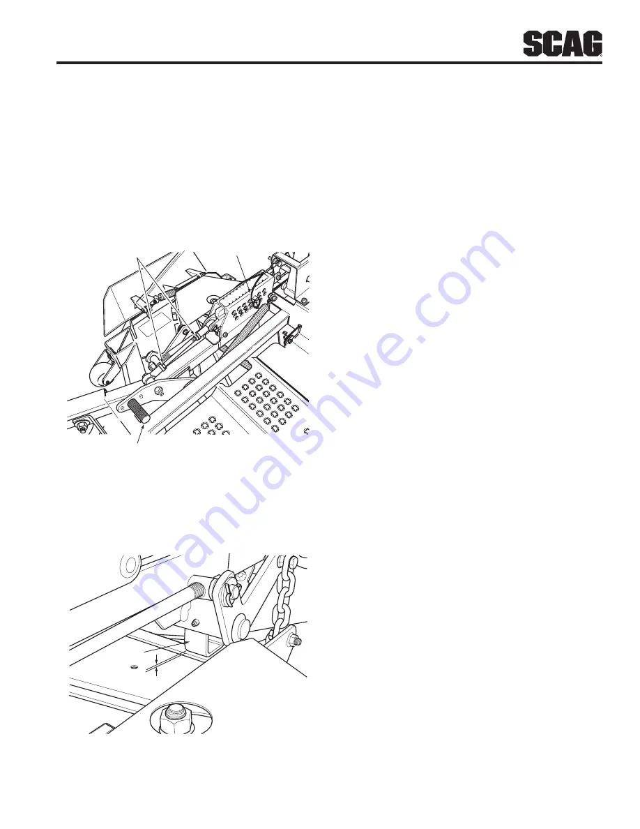
Loosen the jam nuts on both ends of the deck height 
control rod. (See Figure 6.7)

390S014A-2

CUTTING

HEIGHT

6

5.5

5

4.5

4

3.5

3

2.5

2

1.5

1

48

154

3

HEIGHT ADJUSTMENT PEDAL

LANYARD 
PIN

LOOSEN HERE

Cutter Deck Height Adjustment

Figure 6-7. 

Turn the control rod (See Figure 6.7) until there is a 

2. 

1/4" space between the rear deck stop and the top 
of the cutter deck. (See Figure 6.8). Tighten the jam 
nuts on the control rod.

1/4"

DECK
STOP

390S0175-1

Cutter Deck Stop

Figure 6-8. 

Check the cutter deck cutting height by placing the 

3. 

lanyard pin in the 3" position on the cutting height 
index. Release the deck from the transport position 
and allow the deck to move to the 3" cutting height 
position.

Check the measurement from the floor to the 

4. 

cutter blade tip. If the measurement is not at 3", 
an adjustment can be made using the deck height 
control rod. (See Figure 6.7)

- NOTe -

If an adjustment had to be made, be sure that the 
cutter deck can easily be locked into the transport 
position.

Summary of Contents for Turf Tiger STT-31EFI

Page 1: ...ns and safety information for your Scag mower Reading this manual can provide you with assistance in maintenance and adjustment procedures to keep your mower performing to maximum efficiency The speci...

Page 2: ...specially the grass discharge chute Before performing any maintenance or service stop the machine and remove the spark plug wire and ignition key If a mechanism becomes clogged stop the engine before...

Page 3: ...10 3 3 Power Head 10 3 4 Cutter Deck 11 3 5 Hydraulic System 11 3 6 Weights And Dimensions 11 3 7 PRODUCTIVITY 11 OPERATING INSTRUCTIONS SECTION 4 12 4 1 Controls And Instrument Identification 12 4 2...

Page 4: ...er Blades 37 7 10 Tires 38 7 11 Cutter Deck Gearbox 39 7 12 Cooling System 39 7 13 Body Deck And Upholstery 40 ILLUSTRATED PARTS LIST SECTION 8 41 8 1 Scag Approved Attachments And Accessories 41 61V...

Page 5: ...9 0 3 4 9 2 0 7 3 3 4 9 6 7 5 4 3 4 9 9 1 3 8 2 4 9 9 8 9 4 8 5 1 1 8 6 1 7 5 8 2 6 4 1 6 5 8 3 2 7 0 8 5 8 6 5 0 1 8 Mower Serial Number Plate Location Figure 1 1 GENERAL INFORMATION USE ONLY SCAG AP...

Page 6: ...On Start Spring Tension on Idler Off Stop Oil Falling Hazard Thrown Object Hazard Fast Slow Continuously Variable Linear Cutting Element Basic Symbol 481039S Pinch Point Cutting Element Engage Hour me...

Page 7: ...y and possible death carefully read the message Be sure to fully understand the causes of possible injury or death Signal Word It is a distinctive word found on the safety decals on the machine and th...

Page 8: ...revent spillage Clean up any spillage before starting the engine DO NOT add fuel to a running or hot engine Allow 12 the engine to cool for several minutes before adding fuel Never fuel indoors or ins...

Page 9: ...s engaged 13 Take all possible precautions when leaving the 14 machine unattended such as disengaging the mower lowering the attachments setting the parking brake stopping the engine and removing the...

Page 10: ...em should be replaced immediately Roll over protection system 2 5 WARNING Keep the roll bar in the raised and locked position and the seat belt securely fastened during operation Failure to do so coul...

Page 11: ...ed when turning operating on slopes slick or wet surfaces Allow extra distance to stop Stay off of slopes too steep for safe operation To check a slope attempt to back up it with the cutter deck down...

Page 12: ...s NEVER straighten or weld blades Keep all parts in good working condition Replace all 10 worn or damaged decals Use jack stands to support components when 11 required Carefully release pressure from...

Page 13: ...97 483406 483407 483402 484320 483407 483633 483425 483300 WARNING Operation of this equipment may create sparks that can start fires around dry vegetation A spark arrestor may be required The operato...

Page 14: ...rol Mower Engagement BBC Parking Brake Instrument Panel Volt Meter Key Switch Throttle Lever BBC Switch Fuses and Safety Start module Water Temperature Gauge Fuses Two 2 20 Amp Power Head 3 3 Drive Sy...

Page 15: ...pindle Shaft Cast Housing Taper Roller Bearing Low Maintenance with Top Access Grease Fitting and Grease Overfill Relief Poppet Spindle Pulleys Split Steel with Easily Removed Taper Hubs Cutter Deck B...

Page 16: ...he deck drive Engine Throttle Control Figure 4 1 3 Used to control the engine speed Pushing the lever forward increases engine speed Pulling the lever back decreases engine speed Full back position is...

Page 17: ...transport position Cutting Height Adjustment Figure 4 1 13 Used to set the cutter deck at the desired cutting height Deck Release Lever Figure 4 1 14 Used to lock the cutter deck in the transport posi...

Page 18: ...ery life Allow engine to warm before operating the mower 8 Ground Travel And Steering 4 5 IMPORTANT If you are not familiar with the operation of a machine with lever steering and or hydrostatic trans...

Page 19: ...le traveling in reverse allow the right steering control lever to move forward The further the control is allowed to move forward the quicker the mower will turn right To stop the reverse travel allow...

Page 20: ...es properly inflated 6 Parking The Mower 4 8 Park the machine on a flat level surface only Do not 1 park the machine on an incline Place the steering control levers in the neutral 2 position Disengage...

Page 21: ...Cut grass when it is dry and not too tall Do not cut 3 grass too short cut off 1 3 or less of existing grass for best appearance Mow frequently Keep mower and discharge chute clean 4 When mowing wet o...

Page 22: ...B Rotate the steering lever forward or backward to achieve the optimum operating position C Tighten the tension knob and repeat on the opposite side D While in the operator s position bring the steer...

Page 23: ...h towed equipment except at the hitch point Follow manufacturer s recommendations for weight 3 limit for towed equipment 250 lbs maximum towing weight NEVER tow on slopes The weight of the towed 4 equ...

Page 24: ...ng Strips of Uncut Grass in Cutting Path Width of Deck SGB018 Dull worn blades Sharpen blades Incorrect blade sharpening Sharpen blades Low engine RPM Run engine at full RPM Belt slipping Adjust belt...

Page 25: ...er Bent spindle area See your authorized SCAG dealer Dull blade Sharpen blade Uneven Cut on Uneven Ground WavyAppearance High Low Scalloped Cut or Rough Contour Width of Deck SGB021 Uneven ground May...

Page 26: ...t Ground speed too fast Slow speed to adjust for conditions Wet grass Cut grass after it has dried out Step Cut Ridge in Center of Cutting path Width of Deck SGB024 Blades not mounted evenly Adjust pi...

Page 27: ...turning the rod until the proper distance is achieved See Figure 6 1 Tighten the jam nuts With the brake in the engaged position check the 4 spring compression between the two flat washers on the LH...

Page 28: ...ing control rod and turning the rod until the drive wheel turns in the forward direction Turn the rod back until the drive wheel stops moving Turn the rod an additional 1 2 turn See Figure 6 3 390S014...

Page 29: ...eft it is an indication 2 that the right wheel is turning faster than the left wheel To adjust this condition proceed as follows A Stop the machine and place the steering control levers in the neutral...

Page 30: ...on the RH side of the machine Tighten the two elastic stop nuts to secure the cutter 3 deck in the proper position Cutter Deck Pitch The pitch of the cutter deck should be equal between the front and...

Page 31: ...eight Adjustment Figure 6 7 Turn the control rod See Figure 6 7 until there is a 2 1 4 space between the rear deck stop and the top of the cutter deck See Figure 6 8 Tighten the jam nuts on the contro...

Page 32: ...ure 6 9 Placing the baffle in either the 4 3 4 or 5 1 4 setting will enhance fall cutting leaf pickup and reduce cutter deck blowout To adjust the Custom Cut Baffle height Place the cutter deck in the...

Page 33: ...e 6 10 INSPECTION WINDOW x3 Clutch Air Gap Adjustment Figure 6 10 Locate the inspection windows on the clutch 1 Place a 0 015 feeler gauge in the slot between the 2 rotor and the armature Tighten or l...

Page 34: ...essure See paragraph 7 10 X Inspect seat belt for wear or damage See paragraph 2 5 X Check the operator interlock system See paragraph 4 2 X Check coolant level See paragraph 7 11 X Change engine oil...

Page 35: ...llcranks 100 Hours Bi Weekly Chassis Grease 4 5 Cutter Deck Pusharms 100 Hours Bi Weekly Chassis Grease 2 6 PTO Spindle 40 Hours Weekly Lithium MP White Grease 2125 1 7 Cutter Deck Spindle 40 Hours We...

Page 36: ...UBRICANT INTERVAL LITHIUM MP WHITE GREASE 2125 40 HOURS WEEKLY CHASSIS GREASE 100 HOURS BI MONTHLY CHASSIS GREASE 200 HOURS MONTHLY 4 1 6 3 5 7 2 CHASSIS GREASE 500 HOURS YEARLY 390S0145 1 1 8 4 3 9 5...

Page 37: ...aulic System 7 3 A Checking Hydraulic Oil Level The hydraulic oil level should be checked after the first 10 hours of operation Thereafter check the oil after every 200 hours of machine operation or m...

Page 38: ...er Element The hydraulic oil filter should be changed after every 500 hours of operation or annually whichever occurs first Remove the oil filter element and properly discard it 1 See Figure 7 3 Fill...

Page 39: ...ontact with the rim of fuel tank 8 or container opening at all times until fueling is complete Do not use a nozzle lock open device If fuel is spilled on clothing change clothing 9 immediately and was...

Page 40: ...d can cause SEVERE CHEMICAL BURNS Avoid contact of fluid with eyes skin or clothing Use proper protective gear when handling batteries DO NOT tip any battery beyond 45 angle in any direction If fluid...

Page 41: ...eering control will be lost which could result in serious injury or death Replace the pump drive belt as needed or every 400 hours 2 years whichever occurs first Cutter Blades 7 9 A Blade Inspection R...

Page 42: ...r blades remove the nut from the blade attaching bolt Remove the cutter blade bolt and spacer from the spindle shaft See Figure 7 9 NOTE The front of the machine will have to be raised slightly to rem...

Page 43: ...ation or yearly whichever occurs first Place a suitable container beneath the cutter deck 1 gearbox and locate the gearbox drain plug Remove the drain plug drain the lubricant into the 2 container and...

Page 44: ...hot engine with water use only compressed air to remove debris Re install the debris screen to the radiator 3 C Checking The Fan Belt Tension Liquid Cooled Engines Only Periodically check the fan belt...

Page 45: ...this machine Scag approved attachments and accessories GC STT SCZ 61V p n 9091 Requires p n 9096 GC STT SCZ CS61V p n 9095 Requires p n 9096 Install GC STT 61V p n 9096 Mulch Plate p n 9288 920F Hurr...

Page 46: ...5 45 62 58 56 61 61 7 11 79 57 20 57 2 69 10 26 42 39 21 74 73 23 24 22 20 20 27 30 14 29 32 33 28 35 31 25 43 44 44A 34 30 52 51 54 55 2012 STT61V CD 4 7 78 6 59 50 63 49 22 20 47 44A 60 46 6 7 48 7...

Page 47: ...X X X X X X X X X X X X X X X X X X X X X X X X X X X X X X X X X 45 46 47 48 49 50 51 52 53 54 55 56 57 58 59 60 61 62 63 64 65 66 67 68 69 70 71 72 73 74 75 76 77 78 79 80 81 82 83 84 85 86 87 4248...

Page 48: ...CK CONTROLS STT2006CDC 21 19 37 42 4 6 14 10 42 5 2 3 35 23 41 38 32 34 30 7 27 33 40 41 28 28 24 26 41 40 CUTTER DECK 13 40 39 31 41 40 39 43 9 8 45 20 18 36 16 44 17 41 40 26 11 29 22 40 41 15 22 41...

Page 49: ...6 Elastic Stop Slide Weldment Height Adjustment Spacer Decklift Pedal Pin Decklift Swivel Joint LH Swivel Joint RH Bellcrank Weldment LH Rear Bellcrank Weldment RH Rear Locknut 3 8 16 Center Lock Guid...

Page 50: ...METAL COMPONENTS STT 2011 SMC 48 50 26 30 25 12 15 19 9 1 23 24 31 32 33 34 29 33 36 37 40 39 38 41 42 43 51 35 44 45 15 27 22 4 20 28 15 14 13 12 11 10 16 17 20 5 8 7 18 18 4 A A 6 49 47 46 3 8 B B...

Page 51: ...ut 3 8 16 Elast Stop Main Frame w Decals Nut Hex Serrated Flange 3 8 16 Screw Hex Serrated Flange 3 8 16 x 1 Fender Weldment LH Foot Plate Nut Hex Elastic Stop 3 8 16 Bolt Hex Head 3 8 16 x 1 Bolt Hex...

Page 52: ...48 R Section 8 STT ROLL OVER PROTECTION SYSTEM 2 3 4 4 2 3 4 3 4 1 1 1 7 8 6 9 5 7 5 11 10 11 6 10 9 2 5 5...

Page 53: ...04001 87 04021 19 04040 13 484168 04001 163 04021 19 425478 484170 484169 484167 STT ROPS Bolt Hex Head 1 2 13 x 4 Nut Center Lock 1 2 13 Flatwasher 1 2 562 x 1 375 x 109 Pin Assembly incl 9 10 Bolt...

Page 54: ...t Bolt Hex Head 7 16 20 x 1 Flatwasher 7 16 500 x 1 25 x 083 Retractable Seat Belt Armrest Only Armrest Assembly Kit LH Armrest Assembly Kit RH Back Cushion Kit Lumbar Kit Knob Kit Shock Absorber Kit...

Page 55: ...51 R Section 8 NOTES...

Page 56: ...0 3 47 46 47 43 42 4 41 45 59 53 8 54 72 5 6 64 63 62 7 52 55 9 60 61 10 11 56 52 12 15 65 58 52 14 13 12 20 17 45 18 66 19 67 45 56 21 57 58 52 22 18 23 24 49 50 69 25 26 27 28 29 30 36 35 34 33 32 3...

Page 57: ...ck Drive Idler Arm Weldment Pump Drive Driveshaft Liquid Cooled Engine Set Screw 3 8 16 x 3 4 Torx Socket Screw 10 32 x 56 Flatwasher 3 8 391 x 938 x 105 Pin Rue Cotter 3 8 Dia Stud Anti Rotation Pump...

Page 58: ...NGINE ATTACHING PARTS 31HP EFI KOHLER STT 2009 EAPKH EFI 8 9 6 10 FRAME REF PUMP MTG WELDMENT 11 1 3 5 2 10 12 10 12 10 12 13 14 17 15 16 7 4 18 19 20 21 22 23 24 13 A A 11 16 25 26 27 28 29 30 31 32...

Page 59: ...n Engine Kohler 31HP EFI Aegis Available only through Kohler Bolt Hex Hd 3 8 16 x 1 Lockwasher 3 8 Spring Bolt Hex Hd 3 8 16 x 1 3 4 Nut Hex Elastic Stop 3 8 16 Bolt Hex Hd 3 8 16 x 1 1 4 Plate Engine...

Page 60: ...48 47 46 42 43 44 45 15 56 70 69 71 62 65 64 67 60 52 51 50 34 35 TO RH PUMP TO LH PUMP 37 36 27 28 35 33 78 34 31 30 29 8 9 32 13 B 9 B 25 18 72 49 55 54 75 26 5 68 66 37 36 61 59 74 7 20 13 14 22 1...

Page 61: ...Tube Control Link Liquid Cooled Engine Nut Hex 3 8 24 LH Thread Rod End Male 3 8 24 LH Thread Locknut 5 16 18 Elastic Stop Gas Damper Rod End 3 8 24 RH Female Grease Fitting Lever Parking Brake Incl...

Page 62: ...D E F C I H G G F E A A B C DUMP VALVE B 2011 STT HS eps I H 39 23 24 26 40 34 25 35 21 31 33 9 30 30 11 12 13 7 4 4 3 44 45 17 46 16 14 15 32 5 4 4 5 42 34 25 35 18 8 20 19 6 22 41 27 28 29 30 38 Z 2...

Page 63: ...racket RH Oil Cooler Flatwasher 3 8 391 x 938 x 105 Grade 8 Nut Hex Elastic Stop 3 8 16 Pump w Fan Right Hand Bolt Hex Head 3 8 16 x 1 1 4 Nut Hex Elastic Stop 3 8 16 Pump w Fan Left Hand Block Pump C...

Page 64: ...1EFI FS EPA Phase 3 eps Z Z 1 2 3 4 5 6 7 8 9 10 10 10 10 11 11 12 Tank Purge A B To Engine Purge Port B C A C 17 18 19 20 21 21 22 23 24 25 26 27 28 28 32 29 30 31 18 18 19 10 To Engine Fuel Return 1...

Page 65: ...eturn Order by Inch 16 482703 Return Fitting Straight 17 484279 02 Tube Fuel Tank Insert 6 18 48059 05 Clamp Vapor Recovery Hose 3 16 19 48059 02 Clamp Fuel Hose 7 32 ID 20 484342 Carbon Canister 21 0...

Page 66: ...n 8 BDP 16A HYDRAULIC PUMP ASSEMBLY WITH COOLING FAN OR OR PORT A SIDE PORT B SIDE Overhaul Seal Kit 1 2 3 4 5 6 7 8 9 10 11 12 13 14 15 16 17 17 18 19 20 20 21 21 22 23 24 25 26 27 28 29 30 31 32 33...

Page 67: ...287 HG51348 HG52016 HG52014 HG52256 HG44809 Overhaul Seal Kit Shroud Cylinder Block Kit 16cc Thrust Ball Bearing Assembly Variable Swashplate Slot Guide Trunnion Arm Block Spring Block Thrust Washer S...

Page 68: ...TRICAL SYSTEM 31HP EFI KOHLER S C A G P O W E R E Q U IP M E N T 21 28 1 3 4 5 6 13 17 STT2008 ESKH EFI 10 11 17 18 15 14 20 22 23 24 25 26 28 29 30 14 15 9 10 11 8 B B 7 15 14 16 A 31 18 A C C 12 32...

Page 69: ...Lockwasher 5 8 Internal Instrument Panel Top w Decals Key Switch Switch PTO 10 Amp Relay Lockwasher 10 External Tooth Nut Hex 10 32 Water Temp Gauge Base Instrument Panel Lockwasher 1 4 Bolt Hex Hd 1...

Page 70: ...NUAL 481568 FORWARD REvERSE F R 11 482508 PULL OUT TO ENGAGE ON START PUSH IN TO DISENGAGE OFF MOWER DECk Heavy Duty Commercial 481971 10 PUSH IN TO DISENGAGE MOWER DECk PULL OUT TO ENGAGE 22 CHECk EN...

Page 71: ...elocity Plus Decal Fuel Tank Decal Patents Decal Traction Control Decal Heavy Duty Commercial Decal Metalcraft Made In USA Decal Belt Cover Decal Instrument Panel Upper Air Cooled Decal Instrument Pan...

Page 72: ...ARTER B FUEL PUMP ENGINE DIAGNOSTIC LIGHT POS NEG ENGINE PLUG PINK BROWN RED W WHITE STRIPE GRN W WHT STRIPE GRN W BLK STRIPE LIGHT BLUE BLUE BLACK RED RED RED RED RED RED RED RED RED RED RED RED RED...

Page 73: ...the expense of returning it to the owner after repair will be paid for by the owner Scag s responsibility is limited to making the required repairs and no claim of breach of warranty shall be cause fo...

Page 74: ...2012 Scag Power Equipment Division of Metalcraft of Mayville Inc...

Reviews: