


7
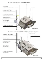
2.2 Diagram of a standard installation single speed.
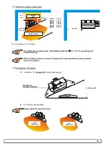
2.3 Diagram of a standard installation double speed
Filter
Control unit
Main solenoid valve
230V ~
L + N + Pe
(see 2.10
page
19)
Governor ( )
( )
*
*
Use appropriate gas governor if P
G
is greater than the
nominal pressure P of the heaters.
P
G
Main valve
Individual valve
3 x 0.75mm²
RP3
Flexible hose
BA connector
Sensor
(supplied with control modul)
XFR single speed heater
Sensor cable
(to be ordered separately)
Filter
Main solenoid valve
230V ~
L + N + Pe
(see 2.10
page
19)
Governor ( )
*
*
Use appropriate gas governor if P
G
is greater than the
nominal pressure P of the heaters.
P
G
Main valve
Individual valve
4 x 0.75mm²
RP32
2 flexibles hose
2 BA connector
Sensor
(supplied with control modul)
XFR double speed heater
Sensor cable
(to be ordered separately)
Control unit