


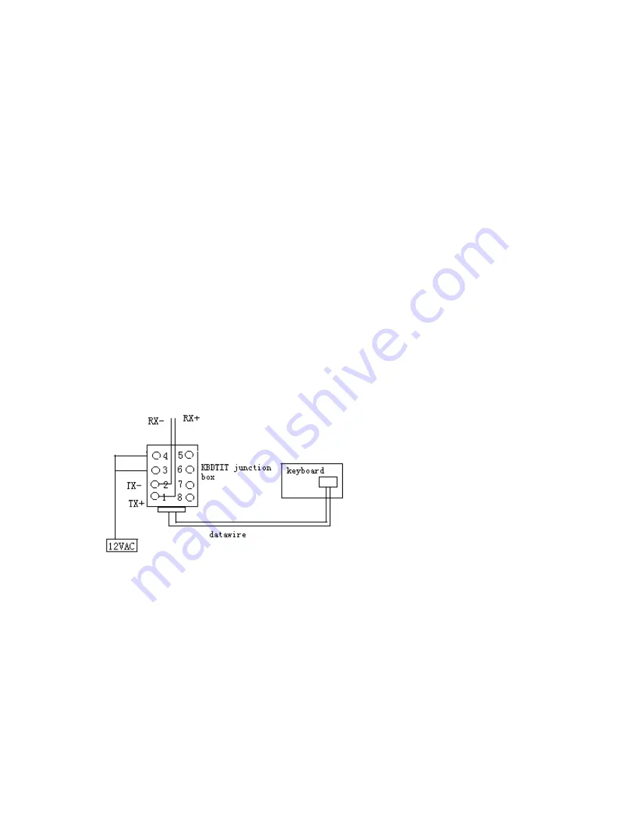
5.
At the wall block wire the transformer to pins 3 and 4. Polarity is
unimportant.
6.
Replace the cover on the wall block. A double-sided sticky pad is
provided to mount the wall block. Secure the wall block to a suitable
surface.
7.
Set the keyboard DIP switches according to the instructions in the
Switch
Settings
section.
8.
Plug in the keyboard data cable.
9.
Plug the DVW-KBD-D transformer into a suitable outlet. The LED
display shows number 1, which is the default camera number.
10.
Go to the
Programming and Operation
section and program and test for
proper operation
SWITCH SETTINGS
To set the switches on the keyboard (refer to Figure 12):
1.
Remove the two screws and the DIP switch cover plate from the rear
of the keyboard.
2.
Set the switches:
Address (Switches 1-4) Position the switches according to Table A.
Each keyboard in the system must have a different address, including
- 3 -


