background image

EN 

1

10 

ELECTRICAL CONNECTION 

• Connect the hood to the mains through a two-pole switch

having a contact gap of at least 3 mm.

• Remove the grease filters (see paragraph Maintenance)

being sure that the connector of the feeding cable is cor-
rectly inserted in the socket placed on the side of the fan.

Chimney Assembly 

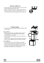
• Fasten the Chimney fixing element 

19

 to the Body using

4 screws 

12c

.

Upper chimney 

• Open the two side pieces out slightly, hook them up be-

hind the brackets 

7.2.1

 and bring them back together

again until they are in contact.

• Fix to the Brackets at the sides, using 4 screws 

12c

 (2.9 x

9.5) provided.

• If there are any, make sure that the Connector extensions

outlet is in correspondence with the Chimney openings.

Lower chimney  

• Open the two side pieces of the Chimney out slightly,

hook them between the upper chimney and the wall, and
then close them together again until they are in contact.

• Fix the part at the sides to the Chimney fixing element

19

, using 2 screws 

12c 

(2.9 x 9.5) provided.

Summary of Contents for NOPPA

Page 1: ...NOPPA Instructions Manual K ytt ohje...

Page 2: ...2 2 INDEX SAFETY INFORMATION 3 CHARACTERISTICS 6 INSTALLATION 8 USE 11 CARE AND CLEANING 12 SIS LT TURVALLISUUSTIETOJA 13 MITAT JA OSAT 16 ASENNUS 18 K YTT 21 PUHDISTUS JA HUOLTO 22 EN FI...

Page 3: ...height please refer to the paragraphs on working dimensions and installation If the instructions for installation of the gas hob specify a greater distance this must be respected Check that the mains...

Page 4: ...to be adopted for fume discharging it is important to closely follow the regulations pro vided by the local authorities WARNING Before installing the Hood remove the protective films Use only screws a...

Page 5: ...ls not applicable to appliances that only discharge the air back into the room The symbol on the product or on its packaging indicates that this product may not be treated as household waste Instead i...

Page 6: ...comprising 2 1 1 Upper chimney 2 2 1 Lower chimney 9 1 Reduction flange 150 120 mm 10 1 Damper 150 15 1 Air Outlet Connector 19 1 Chimney Fixing Element Ref Q ty Components for Installation 7 2 1 2 Up...

Page 7: ...imensions 450 380 430 126 81 41 5 300 260 62 5 340 MIN 460 MAX 660 MIN 340 MAX 660 400 MIN 875 MAX 1075 MIN 755 MAX 1075 6 Dimensions of the hood in ducting version Dimensions of the hood in recycling...

Page 8: ...the first bracket X height of the Upper chimney provided aligning its centre grooves with the vertical reference line Mark the centres of the holes in the bracket Mark a reference point as indicated a...

Page 9: ...stall a 150 pipe To install the dumper 10 Fix the pipe in position using sufficient pipe clamps not supplied To install a 120 pipe To install a 120 mm air exhaust connection insert the reducer flange...

Page 10: ...pen the two side pieces out slightly hook them up be hind the brackets 7 2 1 and bring them back together again until they are in contact Fix to the Brackets at the sides using 4 screws 12c 2 9 x 9 5...

Page 11: ...Fixed When pressed briefly turns the Motor on at Speed three Flashing Pressed for 2 Seconds Activates Speed four with a timer set to 6 minutes after which it returns to the speed that was set previou...

Page 12: ...em to dry before refitting When refitting the filters make sure that the handle is visible on the outside Activated charcoal filter Recirculation version These filters are not washable and cannot be r...

Page 13: ...allit voidaan asentaa alemmas katso ty ja asennusmittoja koskevaa kappaletta Jos kaasuk ytt isen keittotason asennusohjeet m r v t ett et isyyden on oltava yll mainittua suurempi ohjeita on noudatetta...

Page 14: ...suuteen liittyvien toimenpiteiden suhteen on noudatettava tarkkaan paikallisten viranomaisten antamia m r yksi VAROITUS Poista suojakalvot ennen liesituulettimen asentamista K yt vain liesituulettimel...

Page 15: ...a k ytet n samanaikaisesti kaasulla tai muilla polttoaineilla toimivien laitteiden kanssa ei koske laitteita jotka poistavat tilaan vain ilmaa Merkki tuotteessa tai sen pakkauksessa osoittaa ett tuote...

Page 16: ...mi jossa on 2 1 1 Yl hormi 2 2 1 Alahormi 9 1 Sovituslaippa 150 120 mm 10 1 Venttiilill varustettu laippa 150 15 1 Ilman ulostuloliitos 19 1 Hormin kiinnityksen kulmaosa Viite Lkm Asennuksen osat 7 2...

Page 17: ...FI 1 17 Mitat Liesituulettimen imuversion mitat Liesituulettimen suodatusversion mitat 450 380 430 126 81 41 5 300 260 62 5 340 MIN 460 MAX 660 MIN 340 MAX 660 400 MIN 875 MAX 1075 MIN 755 MAX 1075 6...

Page 18: ...isen tuen alapuolelle X toimitetun yl hormin korkeus niin ett sen keskikohta kolot on pystysuoran viitelinjan kohdalla Merkitse tuen reikien keskipisteet Merkitse kuten kuvassa viitepiste 105 mm vaaka...

Page 19: ...ppa 10 150 liesituulettimen rungon ulostu loon Kiinnit putki sopivilla puristimilla Materiaali ei kuulu toimitukseen Putkiliit nt 120 Jos k yt t putkea 120 mm laita kavennuslaippa 9 asentamaasi laippa...

Page 20: ...hormin kiinnityksen kulmaosa 19 vaippaan Yl hormi Levit sivureunoja hieman kiinnit ne tukien 7 2 1 taakse ja sulje ne paikalleen Kiinnit tuet sivuilta 4 toimitetulla ruuvilla 12c 2 9 x 9 5 Varmista et...

Page 21: ...ella T3 Nopeus Kiinte Lyhyt painallus k ynnist moottorin kolmannella nopeudella Vilkkuva Kun painiketta painetaan 2 sekunnin ajan Aktivoi nelj nnen nopeuden joka toimii 6 minuuttia Ajastetun ajan p ty...

Page 22: ...ennen niiden paikalleen asettamista Asenna ne paikalleen ja pid kahva n kyviss ulkopuolella Aktiivihiilisuodatin Suodatinversio Suodattimia ei voi pest eik uudistaa vaan ne t ytyy vaihtaa v hint n ne...

Page 23: ......
Page 24: ...991 0582 438_ver2 191023 D00005812_01...

Reviews: