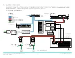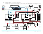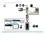
Savant Power System Wiring and Installation Deployment Guide
Copyright 2022 Savant Systems, Inc
009-2222-02 | 080122
- 4 -
1. Before You Begin
This document assumes the installer has read all relevant third party documentation. Read this document in its entirety before starting deployment of any product listed
within. Ensure that the following items are available:
1.
Smart Host (SHR-2000) ..............................................................................................................................................................................................................................................................................................
OR
2. Pro Host or Super Pro Host (SVR-5100, SVR-7000S) ......................................................................................................................................................................................................................................
AND
3. Smart Controller (SSC-0012 or any controller with available GPIO ports) ..............................................................................................................................................................................................
IMPORTANT NOTE!:
A
Smart Controller with RS485 ports
is required for all Sol-Ark deployments, regardless of Host type.
4. Panel Bridge Controller (PBC-1000) .......................................................................................................................................................................................................................................................................
5. OPTIONAL: Smart Energy Monitor (SEM-2015) .................................................................................................................................................................................................................................................
1.1. Power Source Considerations
Before starting installation, it is important to note if an energy storage system will be installed. The Savant Power System can be integrated with an automatic generator,
battery, or microgrid energy storage system for a complete energy management experience. A device that produces energy within the Savant Power System is referred to as a
Power Source
. This Wiring and Install Guide includes instructions on how to integrate all three types of Power Sources. Review the following notes on specifications for Power
Source compatibility before choosing a Power Source. Only one Power Source can be integrated at a time.
Savant
–
IMPORTANT!:
All Savant Hosts
must be backed up by a Universal Power Supply
(UPS).
Generator Physical Requirements
–
IMPORTANT!:
All Automatic Transfer Switches (ATS) must have
Auxiliary Position-Indicating Contacts
to connect to the GPIO terminals on the Savant Host
or Smart Controller.
–
Auxiliary Position-Indicating Contacts come standard on all commonly sold Generac Model residential ATS.
–
Kohler residential ATS
models RXT and RDT (300A and 400A) can be purchased as an accessory for Kohler model ATS under 300A. They can also be purchased
as an accessory for ASCO ATS, and most other brands.
–
When configuring an Savant Power System to work with a generator, the system needs to map the GPIO input to the ATS position. The ATS position can either be
set to the
Utility Grid
or the
Emergency Backup
source.
–
Review the generator-specific
ATS Operation & Installation
manual for information on the auxiliary contact position.
Generator ATS Mapping
–
ATS position mapping is set using the
Grid Available when ATS GPIO is Low
checkbox within
Tools > Energy Manager
. For more information, see the
Savant Power
System Deployment Guide - Racepoint Blueprint
.
–
When the auxiliary contact is
closed
, the ATS GPIO is
Low
, indicating that the ATS is in the
Feed Input
position (Grid Available).
–
When the auxiliary contact is
open
, the ATS GPIO is
High
, indicating that the ATS is in the
Emergency
position (Grid Unavailable).
–
If the auxiliary contact in the open position, and the ATS GPIO is in the high position, the Automatic Transfer Switch (ATS) is in the
Grid
position. This means grid
power is available.
–
If the auxiliary contact in the closed position and the ATS GPIO is in the low position, the Automatic Transfer Switch (ATS) is in the
Standby
or
Emergency
position.
This means Grid power is unavailable.
Solar
–
Solar values must show negative for production.


