Touch 5.5 in Control Screen V2 QRG | 009-2064-00
45 Perseverance Way, Hyannis, MA 02601
Copyright © Savant Systems, Inc | 220711
2 of 2
Installation
The Savant 5.5 inch Touch Control Screen is designed to be installed in
a single gang configuration.
IMPORTANT!
Box should be oriented using the portrait format
(screw holes oriented at top and bottom).
Mount the Bracket
The Savant Touch Control Screen is designed to be mounted using
either a standard 1-gang electrical box or low voltage 1-gang bracket.
1. Mount a 1-gang standard electrical box or low voltage bracket to an
existing wall. Recommended height to center of box is between 57
and 65 inches (145 – 165 cm) above a finished floor.
1-gang
electrical box
1-gang low
voltage bracket
2. Secure the mounting bracket to the electrical box/bracket using
the two 6-32 x 1 inch screws provided. Position the touch panel
mounting tabs facing outward. See image below.
Tabs Face
Outward
Mounting
Bracket
Make Connections
Connect a Cat 5e/6/7 Ethernet cable (T568A, T568B) to the RJ-45
LAN/PoE port on rear of touch panel. See image below.
Local
Network
To LAN/PoE Port
(RJ-45)
To Router
(PoE)
IMPORTANT INFO!
–
The touch screen is powered through the Ethernet cable. An
802.3af compliant PoE network router is required to power the
display.
–
If a PoE network router is not available, a PoE network injector can
be used.
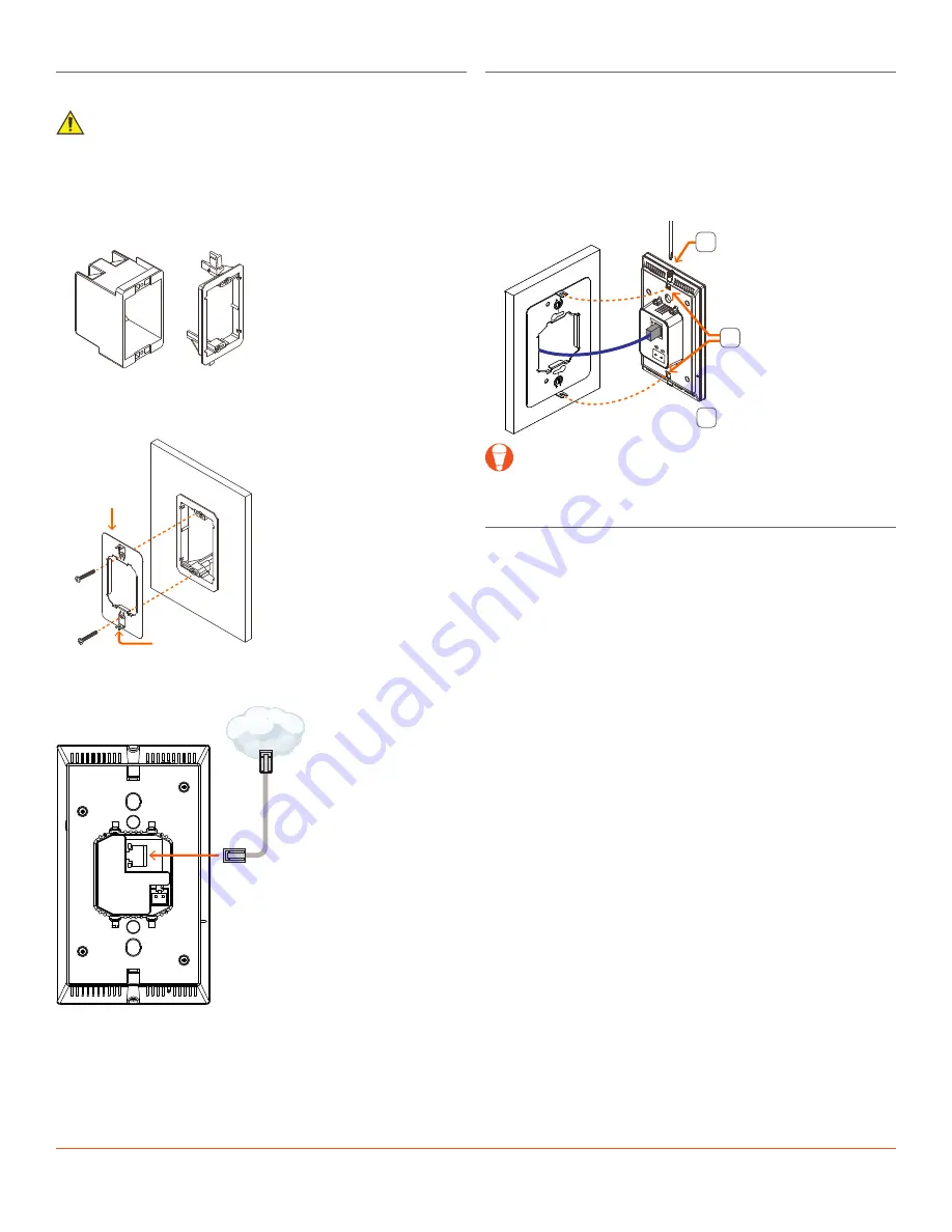
Secure Panel to Bracket
Once cables are connected to rear of touch panel, the panel can be
secured to the mounting bracket installed earlier.
1. Loosen the captive screws on the top and bottom of the touch
panel a few turns to allow the panel to slide into the mounting
bracket.
2. Insert the touch panel into the mounting bracket. Ensure the tabs
on the mounting bracket are inserted into the appropriate slots in
the touch panel.
3. Tighten the two captive screws to secure the touch panel to the
mounting bracket.
3
Loosen captive screws
(top and bottom)
Tighten captive screws
(top and bottom)
Slide touch panel
into slots in
mounting bracket
2
1
TIP!
When installing, the proximity sensor located on the front of
the display should be positioned towards the top.
Apply Power
The ITP-E5500V2 touch panel is powered using PoE via Cat 5e/6/7
Ethernet cable. Connect one end of the Ethernet cable to a PoE
enabled network switch or router, and the other end to the data
connection on the back of the ITP. Once the connection is made,
the ITP will be powered on, and an IP address will be automatically
assigned via DHCP.
Once the ITP is powered and an IP address has been assigned, the
touch panel can be added to a RacePoint Blueprint® configuration. For
details, refer to the
Savant Touch Control Screen Deployment Guide
(009-1475-xx), available on the