


Installation and servicing instructions strictly reserved for qualifi
ed gas installers
25
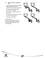
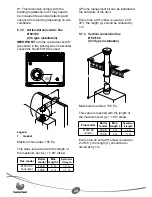
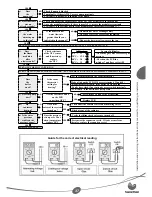
5.7.4 Twin
fl ue 2 x Ø 80
(C53 type installation)
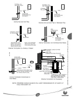
Warning!
Any duct that goes through a wall
and whose temperature is over 60°C
from the room temperature will be
thermally insulated at this passage.
The insulation will be composed of an
appropriate insulating material whose
thickness is ≥ 10 mm and thermal
conductibility λ ≤ 0.04 W/m.K.
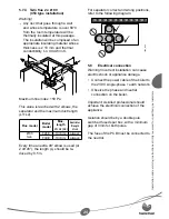
L1
L1
L2
188
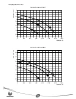
Maximum fl ue index: 150 Pa
This value is reached with 2 elbows, the
separator and the maximum duct length
(L1+L2).
Flue model
Boiler
model
Max.
length
L1+L2 (L2)
Restrictor
if length
L1+L2
Ø 80
twin
F24 E
10 (9) m
always
F30 E
10 (9) m
always
Every time an extra 90° elbow is used (or
2 off 45°), the length (L) should be re-
duced by 0.5 m.
-
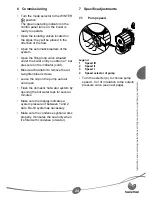
For separator correct and wrong positions,
refer to the following diagram:
1043_R00
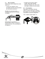
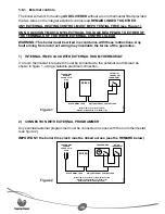
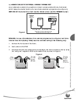
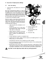
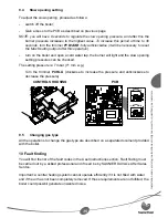
5.8 Electrical
connection
Warning! Incorrect installation can cause
electric shock or appliance damage.
Connect the power cable of the boiler to
the 230 V single-phase + earth network.
Observe the phase and neutral
connection on the boiler.
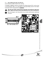
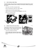
Important: A skilled professional should
achieve the electrical connection of the
appliance.
Isolation should be by a double pole
switched fused spur box, with a minimum
gap of 3mm for both poles.
The fuse of the PCB must be connected to
the neutral.
•
•