


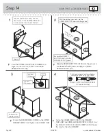


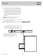


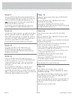

Step 14
å
Insert the DRAWER SIDES (D87 and D88) at an
angle into the slot at each end of the UPPER
DRAWER FRONT (G2).
å
Slide the DRAWER BOTTOM (D729) into the grooves in
the DRAWER SIDES (D87 and D88) and UPPER
DRAWER FRONT (G2).
å
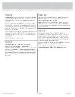
Fasten the DRAWER BRACE (M63) to the UPPER
DRAWER FRONT (G2). Tighten one HIDDEN CAM.
å
Fasten the DRAWER BACK (D61) to the DRAWER
SIDES (D87 and D88) and DRAWER BRACE (M63). Use
five BLACK 1-9/16" FLAT HEAD SCREWS. (30S). Repeat
this step for the other DRAWER.
The tabs should insert freely into the
slots. Gently tilt the DRAWER SIDES side
to side until the tabs slip into the slots.
Surface with
HIDDEN CAM
1
2
3
4
Be sure the DRAWER
BOTTOM inserts into the
DRAWER FRONT groove.
With the palm of your hand, tap the
DRAWER BOTTOM down into the groove.
Groove
Arrow
Maximum
210 degrees
Minimum
190 degrees
Start each screw a few turns before
completely tightening any of them.
BLACK 1-9/16" FLAT HEAD SCREW
(10 used in this step)
30S
G2
G2
G2
VIEW THE T-LOCK BOX VIDEO
D88
D87
D88
D729
D87
D87
D88
D61
Unfi
nished
sur
face
408293
www.sauder.com/services
Page 18
M63
M63