background image

SP-6500 • SD-6000 

SATEL 

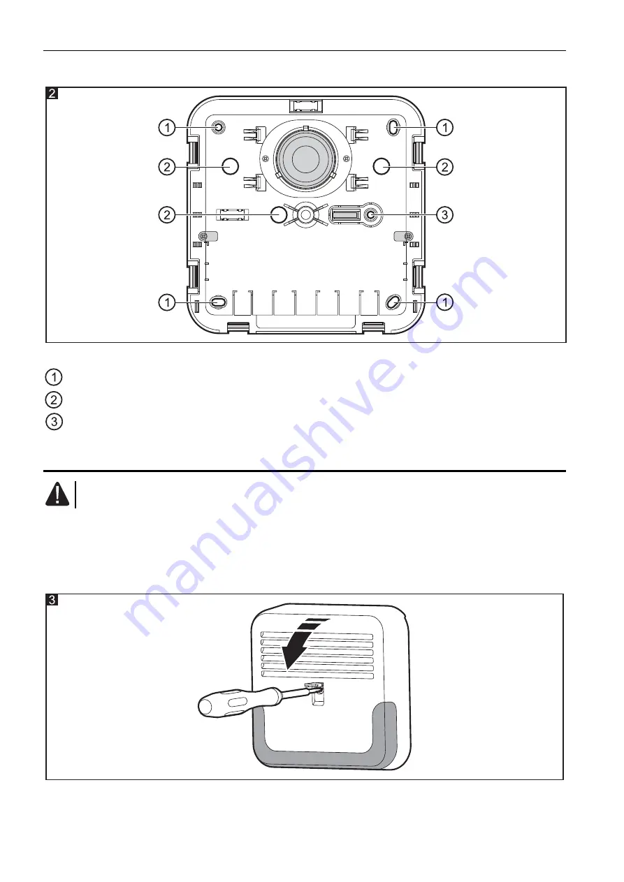
Enclosure base 


Explanations for Fig. 2: 

 mounting hole. 

 cable entry hole. 

 tamper mounting hole. 

4.  Installation and start-up 

Power down the control panel before connecting the siren to it. 

The siren must be installed on the wall, high above the floor, at a hard to access location, so 
as to minimize the risk of tampering. 
1.  Undo the cover locking screw (you do not have to remove it completely) and, holding the 

cover by its edge, pull it open (Fig. 3 shows how the cover should be opened, when the 
hinges are mounted in standard factory position). 


2.  Remove the cover. 
3.  Move aside the catches holding the electronics module and remove it. 

Summary of Contents for SP-6500

Page 1: ...f using two LEDs as indicators and customize their functionality to the user s needs Optional operation with a backup battery Weatherproofed electronic circuit Tamper protection in 2 ways cover remova...

Page 2: ...m Weight SP 6500 1160 g SD 6000 1530 g The declaration of conformity may be consulted at www satel eu ce 3 Description Fig 1 shows the SP 6500 siren with cover open enclosure base piezoelectric transd...

Page 3: ...two LEDs that the alarm signaling cannot be triggered If the signaling must be triggered for test purposes immediately after start up of the siren skipping the 30 second delay do as follows 1 Remove...

Page 4: ...ed as indicators are to operate The LEDs used as indicators are blinking when active The LEDs used as indicators are lit when active 2LED 1LED Allow you to set the number of LEDs used as indicators Th...

Page 5: ...tatus 12 V DC voltage s triggered wh oltage is remo is applied to the input en 12 V DC v Optical signaling is triggered when 0 V voltage is removed inactive status 0 V voltage is applied to the input...

Page 6: ...e installed on the wall high above the floor at a hard to access location so as to minimize the risk of tampering 1 Undo the cover locking screw you do not have to remove it completely and holding the...

Page 7: ...be installed in the siren secure the battery with the holders provided for this purpose and then connect leads to the battery the red lead to the positive terminal the black lead to the negative term...

Page 8: ...5 3 Insert the moving parts of hinges in the holders on the left hand side to open the cover to the right or on the right hand side to open the cover to the left see Fig 6 and Fig 7 SATEL sp z o o ul...

Reviews: