background image

GENERAL

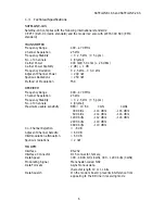
Operating Voltage

+ 10...+ 14 Vdc

Current Consumption

When DTR is "0": 

2,8 mA

When DTR is "1":  

Receiving: 90 mA
Transmitting: 600 mA

Antenna Connector

TNC

50 ohm

,

 female

Size H x W x D

137 x 67 x 29 mm

Installation plate

130 x 63 x 1 mm

Weight

250 g

Temperature Range

- 25 °C...+ 55 °C

Labelling information:

Ser.no.

96052938

Freq.

Ch F 468.200 MHz

SATEL OY

Tel: +358-24-7331033, Fax: +358-24-7331034

w

Serial number


(year+ week + manufacture number)

w

Frequency, set by the manufacturer.  F =  position of the channel switch and the
frequency corresponding  468.200 MHz

w

Manufacturer's contact information

2

Asynchronous Data Transmission

2.1

Asynchronous Characters

Data characters  can be transmitted  either in 10 or 11 bits and   either in 8  or 9 bit data
characters between the start and stop bits respectively. These options are factory set. Thus,
they have to be decided in advance.

Characters are formatted in accordance with the ANSI standard asynchronous characters.
See diagram below.


7 D

S

S

S

S

8 D

8 D

9 D

P L

L

L

L

P

10 bit

11 bit

S = start bit

P = parity bit

L = stop bit

D = data bit

Data transmission between the radio data modems is synchronous. The radio data modem
corrects  the  time  difference  between a  clock  signal  from  the data  transmitting  equipment

SATELLINE-1AS and SATELLINE-2AS


 8

Summary of Contents for SATELLINE-1AS

Page 1: ...SATELLINE 1AS and SATELLINE 2AS Radio Data Modem USER GUIDE ...

Page 2: ...distance of the radio connection 11 4 2 Radio field strength 12 5 Installation 13 5 1 RS 232 Interface 14 5 2 Supply of current 14 5 3 Mounting the antenna 15 6 Equipment 18 6 1 The connection of antennas to radio modems 18 6 1 1 Hand portable equipment 18 6 1 2 Equipment installed in vehicles 18 6 1 3 Base station 18 6 2 Cables 19 6 2 1 RF cables 19 6 2 2 Interface cables 19 7 Check List 20 Appen...

Page 3: ...longer distances because of its better sensitivity The SATELLINE 2AS differs from SATELLINE 1AS by the radio part Both the transmitter and the receiver parts are on the same board transceiver and their function is based on the synthesized radio technique The frequency stability is better and it is possible to change the radio channel The data transmission formed by radio modems resembles a cable U...

Page 4: ...controlled through one of the radio modems or multimaster mode in which any one of the radio modems can initiate the data transmission when the radio channel is free When the radio data modem is in the receiving mode a data squelch facility is incorporated into the modem board to effectively ignore reception of error characters to the RD line which may have been caused by radio interference 1 2 RS...

Page 5: ...ignal ground 8 GND is the ground of supplying voltage 9 RD received data 11 TD input of transmitted data 13 RTS gives radio modem a request to send starts the transmitter answer by CTS line 15 Supply voltage The RSSI Received Signal Strength Indicator is available on the radio data modem This feature indicates the level of field strength of an incoming transmission and is particularly useful in sy...

Page 6: ...e 400 470 MHz Channel Separation 25 kHz Frequency Stability 2 5 kHz 5 ppm No of Channels 1 Crystal Maximum usable sensitivity BER 10 E 4 1AS 1ASl 300 bit s 114 dBm 116 dBm 600 bit s 114 dBm 116 dBm 1200 bit s 112 dBm 116 dBm 2400 bit s 110 dBm 4800 bit s 110 dBm Co Channel Rejection 8 dB Adjacent Channel Selectiv 60 dB Intermodulation attenuation 60 dB Spurious radiations 2 nW MODEM Interface RS 2...

Page 7: ...le by a Hex switch Frequency Stability 1 5 kHz Method of Modulation FSK Transmitter Carrier Power 500 mW 50 ohm 27 dBm Adjustment range 20mW 1 W 50 ohm factory set Carrier Power Stability 1 dB 2 dB Frequency Deviation 2 5 kHz Adjacent Channel Power 200 nW Spurious Radiations I ETSI 300 220 Receiver Sensitivity 108 dBm BER 10 E 4 Co channel rejection 8 dB Adjacent channel selectivity 65 dB Intermod...

Page 8: ... 200 MHz w Manufacturer s contact information 2 Asynchronous Data Transmission 2 1 Asynchronous Characters Data characters can be transmitted either in 10 or 11 bits and either in 8 or 9 bit data characters between the start and stop bits respectively These options are factory set Thus they have to be decided in advance Characters are formatted in accordance with the ANSI standard asynchronous cha...

Page 9: ...y changes on the modem card 2 4 Transmission There are two different methods of initiating data transmission 1 RTS CTS handshaking 2 Data connected directly to TD line The first method using RTS CTS handshaking has to be used for data speeds of 2400 and 4800 bit s This method is initiated from the radio data modem requesting permission to send This is achieved by switching the RTS line from an OFF...

Page 10: ...DBP DBP Data Bit Period e g 2ms 4800 bit s 3 Multi Modem Data Systems 3 1 Required sequence of data characters The data should be transferred in continuous sequences or in sequences divided into blocks Sequences that are too short e g 1 character should not be sent because overhead information synchronization plus terminal address takes a great deal of processing time and thus slows down the data ...

Page 11: ...le stations do not hear each another collisions may occur A multi master protocol is not included in the transparent radio modem It is a protocol of higher hierarchy and supplied by the system 4 Planning a Radio Modem Network 4 1 Factors affecting quality and distance of the radio connection power of radio transmitter sensitivity of radio receiver tolerance of spurious radiations of the radio modu...

Page 12: ... of operation can be increased by dividing the transmitted data into e g 50 500 bits blocks and by retransmitting defected blocks A sufficent safety margin can be obtained by testing communications using an extra 6 dB rejection at the antenna connection and with slightly less effective antennas than those to be used in the final system Saterm test program can be used in the communications testing ...

Page 13: ...By mounting the radio modem directly on the custo mer s equipment 2 By using the velcro type tape supplied with the radio modem 1 By using the installation plate that should be fastened on the back side of the radio modem The installation plate can be mounted using the holes provi ded on installation plate NOTE When choosing the place of mounting please check that water can not get inside the radi...

Page 14: ...below TD RD RTS CTS CD 2 3 4 5 7 8 TD RD RTS CTS SGND CD DTR Vb GND 11 9 13 6 7 2 1 15 8 Vb GND Radio modem FUSE 630 mA slow DTR 20 DSR 6 SGND 3 4 DSR 10 TD RD RTS CTS CD 2 3 5 1 7 8 9 PIN D CONNECTOR DTR 4 DSR 6 SGND 25 PIN D CONNECTOR 5 2 Supply of current The nominal voltage of SATELLINE radio modems is 12 V The range of voltage is 10 14 V Variations in the voltage below 1V are allowed as the r...

Page 15: ...g to the changes of the current consumption of the radio modem This kind of function of the power supply weakens the function of the radio modem or prohibits it totally Supply current should be controlled in situations where the distance is short or the radio field strength is sufficient but the connection does not work or the number of faulty packets is big Quick changes in voltage can not be mea...

Page 16: ...ful to use rather a long antenna cable in order to avoid the installation of radio modems near the antenna into a place possibly difficult to access The antenna cable should be chosen according to the lenght bearing in mind the following recommendations Length Type Attenuation 5 m RG58 3 0 dB 10 m 450 MHz 5 20 m RG213 1 5 dB 10 m 450 MHz 20 m Nokia RFX 1 2 50 0 5 dB 10 m 450 MHz 20 m S12272 4 0 5 ...

Page 17: ...erfering antenna is wanted with the horizontal polarized antennas there must be a good attenuation of the back lobe In addition to this the interfering radiator should be situated behind the antenna When the system does not demand the use of an omnidirectional antenna it is recommendable to use directional antennas e g two element yagis in firm external installations As the antenna amplification i...

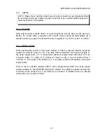
Page 18: ... most suitable It can be mounted at the top of a pipe as this provides it with as much open space as possible In places where the antenna cannot be connected directly to the TNC a 50 ohm coaxial cable must be used to provide the link between the TNC and the antenna 6 1 3 Base station omnidirectional 1 4 1 2 or 5 8 wave antenna directional yagi or corner reflecting antenna The antenna should be ins...

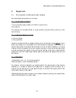
Page 19: ...on of the radio modem it must be observed that the maximum length of an RS 232 cable is 15 m The cable must be shielded The maximum length of the power supply cable is 2 m As standard cables we supply cables with either a 25 pin connector CRS 1 F or CRS 1 M F female M male or with a 9 pin connector CRS 2 F or CRS 2 M The length of the cables are 2 m and they contain both interface and power supply...

Page 20: ... capacity and stability of the power supply must be secured so that the current required by the transmitter is sufficient for creating a reliable connection 4 The antenna is installated according to given instructions 5 The settings of the radio modem correspond those of the terminal and all radio modems of the system have the same settings and are compatible to each other 6 The radio modems are o...

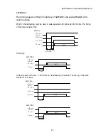
Page 21: ...llowing DATA DTR pin 1 RTS pin 13 CTS pin 6 TD pin 11 30 ms 8 ms wake up time SENDING pwr on DATA DTR pin 1 RD pin 9 CD pin 2 30 ms RECEPTION pwr on In data speeds 300 bit s 1200 bit s no handshaking is needed The timing of the data transfer is as follows DATA DTR pin 1 RTS pin 13 CTS pin 6 TD pin 11 30 ms SENDING pwr on DATA DTR pin 1 RD pin 9 CD pin 2 30 ms RECEPTION pwr on SATELLINE 1AS and SAT...

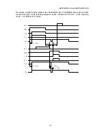
Page 22: ...E 2AS radio modems will become clear in the following diagram It also includes the CD line in the receiving mode of a third radio modem RD1 RTS1 CTS1 TD1 CD1 RD2 RTS2 CTS2 TD2 CD2 CD3 5 10ms 5 10ms 5 10ms 8 10ms 40DBP 40DBP 20 25ms SATELLINE 1AS and SATELLINE 2AS 22 ...

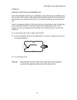
Page 23: ...perating channel is selected by turning this switch Position F of the switch refers to the lowest frequency and 0 to the highest Channels and respective switch positions of the particular device is found at the appendix 3 1 Open the back part of the housing of the modem 2 Turn the hexadecimal switch to the right position The location of the switch is seen at the following diagram HEXADECIMAL SWITC...

Page 24: ... 300 y 325 y 350 y 375 y 400 y 775 MHz y 400 y 425 y 450 y 475 y 500 y 525 y 550 y 575 y 600 y 625 y 650 y 675 y 700 y 725 y 750 y 775 y 800 z 175 MHz y 800 y 825 y 850 y 875 y 900 y 925 y 950 y 975 z 000 z 025 z 050 z 075 z 100 z 125 z 150 z 175 y x 1 z x 2 Hardware settings are made by the manufacturer The frequency range of the equipment is marked on the label on the back of the r adio modem Ex...

Page 25: ...SATELLINE 1AS 2AS RSSI 0 1 2 3 4 5 6 120 115 110 105 100 95 90 85 80 75 70 65 60 55 50 45 40 35 30 25 20 Pin dBm Tolerance 10 dBm RSSI V pin5 load impedance 1 Mohm SATELLINE 2AS SATELLINE 1AS ANHANG 4 ...

Reviews: