SATEL OPU-3P
3
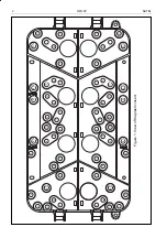
hole marking
devices mounted in the holes
1
INTEGRA 64, INTEGRA 128, CA-64 P
2
CA-10 P, CA-64 PTSA, STAM-1 PTSA, INTEGRA 32, INTEGRA 128-WRL
3
CA-6 P, CA-64 OPS, CA-64 PP, INTEGRA 24, APS-30
4 CA-5,
ACX-201,
ACCO-KP-PS
6 CA-4V1
7
CA-10 E, MST-1, ZB-2
8
CA-64 E, CA-64 SM, MDM56 BO, INT-RS, INT-FI, ISDN-SEP, GPRS-T1,
GPRS-T2
9
CA-64 EPS, CA-64 ADR
10
CA-64 O, CA-64 SR, CA-64 DR, VMG-16, ETHM-1, MP-1, VIVER
11 GSM-4S
12
GSM LT-1S, GSM LT-2S, ACCO-KP, ACU-100, ACX-200
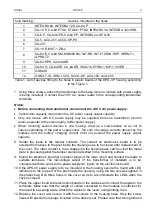
Table 1. List of devices fitting to the holes in plastic inserts of the OPU-3 P housing according
to the Figure 1.
7. Using three screws, attach the transformer to the base (when a module with power supply
is being installed). Connect the 230 V AC power leads to the corresponding transformer
terminals.
Notes:
•
Before connecting the transformer, disconnect the 230 V AC power supply.
•
Transformer capacity must match the DC power supply output capacity.
•
Only one device with DC power supply may be supplied from one transformer (control
panel, expander with power supply, buffer power supply).
•
When mounting several devices in one housing, draw up a load balance so as not to
cause overloading of the power supply used. The sum of average currents derived by the
modules and the battery charging current must not exceed the power supply output
capacity.
8. Solder the leads to the tamper contacts. The contact on electronics board is to be
screwed from above to the post inside the housing so as to be closed after replacement of
the cover. The other contact is to be snapped in the housing base catch so that the metal
plate is pressed against the tamper element attached to the mounting surface.
9. Mount the electronic board(s) on plastic plugs of the lower insert and connect the leads to
suitable terminals. The low-voltage output of the transformer (if installed) is to be
connected with two wires to the power supply AC inputs on the electronics board.
10. If the APS-30 power supply is to be mounted in the housing, secure the board with LED
indicators to the top part of the post inside the housing, using the two screws supplied in
the plastic bag. Drill three holes in the cover so as to accommodate the LEDs when the
cover is closed.
11. Place the upper insert with electronics boards in the catches and connect the leads to the
terminals. Make sure that the length of cables connected to the modules is sufficient for
the insert to be swung aside. Attach the cables to the insert, using binding clips.
12. Replace the cover and secure it with four screws to the housing base. Stop the screw
holes with special hole plugs included in the delivery set. Please note that two right-hand


