Chapter 2 Installation
12
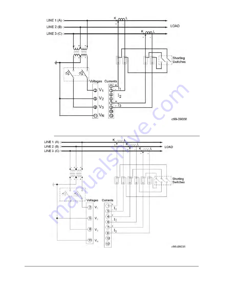
Figure 2-6
Three Wire Open Delta Connection Using 2 PTs, 2 CTs (2-element) Wiring Mode =
3OP2
Figure 2-7
Three Wire Open Delta Connection Using 2 PTs, 3 CTs (2
½
-element)
Wiring Mode =
3OP3
Page 1: ...C192PF8 RPR Power Factor Manager Reactive Power Regulator Installation and Operation Manual BG0347 Rev A1 ...
Page 2: ...C192PF8 RPR Power Factor Manager and Reactive Power Regulator Installation and Operation Manual ...
Page 3: ...rument However these instructions do not cover all possible contingencies that may arise during installation operation or maintenance and all details and variations of this equipment are not covered by these instructions For additional information regarding installation operation or maintenance of this instrument contact the manufacturer or your local representative or distributor IMPORTANT Please...
Page 4: ... to reduce mechanical strain on the screw terminals if necessary Setup procedures must be performed only by qualified personnel familiar with the instrument and its associated electrical equipment DO NOT open the instrument under any circumstances Modbus is a trademark of Modicon Inc Read this manual thoroughly before connecting the meter to the current carrying circuits During operation of the me...
Page 5: ... Relay Operation Control Menu 32 4 8 Display Setup Menu 33 4 9 User Selectable Options Menu 34 4 10 Access Control Menu 36 4 11 Reset Synchronization Menu 37 4 12 Manual Relay Control Menu 38 4 13 PFC Setup Menu 39 4 14 PFC Manual Mode Menu 43 Chapter 5 PFC Setup and Operation 44 5 1 Capacitor Bank Control Options 44 5 2 PFC Operation 45 5 3 Capacitor Banks Protection 52 Chapter 6 Data Display 55 ...
Page 6: ...structions for performing setup for the Power Factor Controller PFC and describes front panel operations in PFC manual mode Chapter 6 Data Display guides you through the display pages Chapter 7 Viewing Status Information tells you how to access additional status information on the instrument This information may be useful during installation Technical Specifications for the C192PF8 RPR are found i...
Page 7: ...n both up and down keys for more than 5 sec RXD TXD LEDs showing communications receive transmit status Setup is menu driven with optional password protection 16 programmable setups are provided for alarm and control functions for programmable parameters see Measured Parameters below Communications are available using an RS 232 or RS 485 standard factory set with Modbus protocol 120 user assignabl...
Page 8: ...lculations Measured Parameters Note Real time values are measured over 1 cycle of fundamental frequency Average values are sliding average of 8 16 or 32 real time measurements Output Parameter Dis play Com Analog Pulse Alarm Average Amps Volts Frequency setup via PC setup via panel Average RMS voltage per phase L N Average RMS voltage per phase L L Average RMS current per phase Average frequency A...
Page 9: ...al active energy import Total active energy export Total reactive energy import Total reactive energy export Total reactive energy net Total reactive energy absolute Total apparent energy Min Max Log Min Max volts Min Max amps neutral current Min Max frequency Min Max kW kvar kVA PF Real time Amps Volts Frequency RT RMS voltage per phase L N RT RMS voltage per phase L L RT RMS current per phase RT...
Page 10: ...se Fundamental Frequency Values H01 Voltage current per phase kW PF per phase kvar kVA per phase Total kW PF Total kvar kVA Phase Rotation Counters Status Input Relay Status Remote Relay Control Alarm Trigger Status Self Diagnostic Tests For 4Ln3 and 3Ln3 wiring configurations line to line and line to neutral voltages are displayed and transmitted via communication simultaneously and can be used a...
Page 11: ...6 Chapter 1 Introduction Instrument Dimensions Figure 1 1 C192PF8 RPR Dimensions ...
Page 12: ...Mechanical Installation Prepare the panel cut out 136 x 136 mm prior to mounting STEP 1 Place the instrument through the cut out STEP 2 Assemble the latches onto the outer wall of the enclosure STEP 3 Tighten the screws Figure 2 1 Mounting the C192PF8 RPR ...
Page 13: ...se an external circuit breaker or switch AC power supply line to terminal 12 neutral to terminal 10 DC power supply positive to terminal 12 negative to terminal 10 2 2 2 Current Inputs Connect the current inputs to terminals 1 3 4 6 7 and 9 The instrument is connected to the current transformer as shown in Figures 2 3 through 2 10 2 2 3 Ground Connect the chassis ground C192PF8 RPR terminal to the...
Page 14: ...Chapter 2 Installation 9 Figure 2 2 C192PF8 RPR Connections Rear View ...
Page 15: ... element 4Ln3 or 4LL3 Figure 2 5 3 wire open delta connection using 2 PTs 2 CTs 2 element 3OP2 Figure 2 6 3 wire open delta connection using 2 PTs 3 CTs 2 element 3OP3 Figure 2 7 4 wire WYE connection using 2 PTs 3 CTs 2 element 3Ln3 or3LL3 Figure 2 8 4 wire delta direct connection using 3 CTs 3 element 4Ln3 or 4LL3 Figure 2 9 3 wire 4 wire connection using the current from one phase 1 CT and the ...
Page 16: ...hapter 2 Installation 11 Figure 2 4 Four Wire WYE Direct Connection Using 3 CTs 3 element Wiring Mode 4LL3 or 4Ln3 Figure 2 5 Four Wire WYE Connection Using 3 PTs 3 CTs 3 element Wiring Mode 4LL3 or 4Ln3 ...
Page 17: ...hapter 2 Installation 12 Figure 2 6 Three Wire Open Delta Connection Using 2 PTs 2 CTs 2 element Wiring Mode 3OP2 Figure 2 7 Three Wire Open Delta Connection Using 2 PTs 3 CTs 2 element Wiring Mode 3OP3 ...
Page 18: ...apter 2 Installation 13 Figure 2 8 Four Wire WYE Connection Using 2 PTs 3 CTs 2 element Wiring Mode 3Ln3 or 3LL3 Figure 2 9 Four Wire Delta Direct Connection Using 3 CTs 3 element Wiring Mode 4LL3 or 4Ln3 ...
Page 19: ...2 Installation 14 Figure 2 10 Three Four Wire Direct Connection Using 1 CT Wiring Mode 2LL1 2 2 6 Relay Eight relays are provided for capacitor bank control or energy pulsing alarms Figure 2 11 Relay Connection ...
Page 20: ...for power demand period Figure 2 12 Status Input Connection 2 2 8 Analog Output The C192PF8 RPR provides one optically isolated analog output with current output options of 0 20 mA and 4 20 mA current loop load of up to 500 Ohm The analog output must be used with a 24 V DC external power supply Figure 2 13 Analog Output Connection ...
Page 21: ... MODEM TxD GND 2 7 C99 11012 3 RxD Figure 2 14 RS 232 Connection for 25 pin Modem Connector 9 PIN DB9 MALE CONNECTOR POWERMETER 14 15 13 RS 232 RxD TxD SG TxD 3 GND 5 c99 11013 MODEM RxD 2 Figure 2 15 RS 232 Connection for 9 pin Modem Connector RS 232 POWERMETER RxD 14 SG TxD 15 13 25 PIN DB25 FEMALE CONNECTOR IBM PC COMPATIBLE RTS CTS 5 4 TxD DTR DSR RxD GND 6 20 2 7 3 c99 11014 Figure 2 16 RS 23...
Page 22: ...uter Connection NOTE Where the manufacturer s RS 232 RS 485 converter is used on a computer connection R1 is not applicable since it is built in to the converter Activity on the communications port lines is indicated via the TXD and RXD LEDs on the front panel and via the Status Information menu see Chapter 6 A full description of the communication protocols may be found in the C192PF8 RPR and Mod...
Page 23: ... 1 presents a complete menu list Depending on the model of your instrument some menus may not appear Password The Setup Change Menu can be secured by a user defined password comprised of 4 digits The instrument is shipped with password protection disabled To enable password protection go to the Access Control Menu see Section 4 10 The Password Menu appears if password protection is enabled To ente...
Page 24: ...le Options Access Control ENTER ENTER PHAS rEL St In Cnt 1 Cnt 2 Cnt 3 Cnt 4 Phase Rotation Relay Status Status Inputs Counter 1 Counter 2 Counter 3 Counter 4 SELECT Selects an active window Enters menu sub menu Quits menu sub menu Scrolls options forward Scrolls options backward ENTER ESC rELo Relay Operation PFC H PFC Manual Mode PFC PFC Setup PFC PFC Status rELc CYC 1 Relay Operation Counter 1 ...
Page 25: ...configuration options which define the general operating characteristics of your instrument such as wiring mode input scales the size of the RMS averaging buffer etc Table 4 1 lists the basic setup options their code names and applicable ranges Activate the middle window to scroll through the list of available options and then activate the lower window to set the option value To select and view a ...
Page 26: ...mand periods 1 15 1 The number of demand periods to be averaged for sliding window demands 1 block interval demand calculation A dP Ampere Volt demand period 0 1800 s 900 The length of the demand period for volt ampere demand calculations 0 measuring peak current buF Averaging buffer size 8 16 32 The number of measurements for RMS sliding averaging rSt Reset enable disable diS En Protects all rese...
Page 27: ...ndow to scroll through the list of available options and then activate the lower window to set the option value To select and view a setup option Press to activate the middle window Use the up down arrow keys to scroll to the desired option The option setting will appear in the lower window To change the selected option Press to activate the lower window Press the up down arrow keys to scroll to t...
Page 28: ... allocate the digital input as an external synchronization input it is automatically configured as a status input External synchronization input To change the digital input allocation Press to activate the middle window Use the up down arrow keys to set the input allocation status Press to store your new inputs allocation Press to leave the allocation unchanged or to quit the menu 1 indicates that...
Page 29: ... the value unchanged Press again to store the setup for the channel To quit the setup without changes From the middle or lower window press To quit the menu From the upper window press or NOTES 1 Except for the signed power factor the output scale is linear within the value range The scale range will be inverted if the full scale specified is less than the zero scale 2 The output scale for the sig...
Page 30: ...kW MW Pmax to Pmax r q Total kvar kvar Mvar Pmax to Pmax r S Total kVA kVA MVA 0 to Pmax r PF Total PF 0 000 to 0 000 r PF LG Total PF lag 0 to 1 000 r PF Ld Total PF lead 0 to 1 000 r Fr Frequency Hz 0 to 100 00 Average Measurements A U 1 Voltage L1 L12 V kV 0 to Vmax A U 2 Voltage L2 L23 V kV 0 to Vmax A U 3 Voltage L3 L31 V kV 0 to Vmax A C1 Current L1 A 0 to Imax A C2 Current L2 A 0 to Imax A ...
Page 31: ...se of their high endurance Available pulsing parameters are listed in Table 4 5 To select a pulse relay Use the up down arrow keys to scroll to the desired relay The pulsing parameter assigned to the relay is displayed in the middle window and the amount of unit hours per pulse is displayed in the lower window To change the pulse relay setup Press to activate the middle window Use the up down arro...
Page 32: ...tor a wide variety of events in turn these events can be programmed to trigger specific actions This menu is used to specify the events to be monitored by the setpoints and actions to be triggered by those events To program a setpoint you might need to define up to six setup parameters which include the setpoint trigger parameter operate and release limits optional operate and release delays and t...
Page 33: ... new setup for the setpoint From the middle window press To quit the setpoint setup without changes From the middle window press To quit the setpoints setup menu From the upper window press or NOTES 1 When you enter the setpoints setup menu at the protected level monitoring of setpoints is temporarily suspended until you return to the main setup menu 2 Each time you select a new trigger parameter ...
Page 34: ...nt disabled Status Input St On Status input ON St OFF Status input OFF Fault Triggers FAult Device Fault diagnostics error no U No Volt UncoP Uncompensated reactive power Phase Reversal POS ro Positive phase rotation reversal NEG ro Negative phase rotation reversal Real time Values on any Phase r Hi U High voltage V 0 to Vmax r Hi LU High L L voltage V 0 to Vmax r Lo U Low voltage V 0 to Vmax r Lo...
Page 35: ...to Pmax Hi d S High block interval kVA demand kVA 0 to Pmax Hi Sd P High sliding window kW demand kW 0 to Pmax Hi Sd S High sliding window kVA demand kVA 0 to Pmax Hi Ad P High accumulated kW demand kW 0 to Pmax Hi Ad S High accumulated kVA demand kVA 0 to Pmax Hi Pd P High predicted sliding window kW demand kW 0 to Pmax Hi Pd S High predicted sliding window kVA demand kVA 0 to Pmax For parameter ...
Page 36: ...ti Cn 1 Count operating time using counter 3 ti Cn 1 Count operating time using counter 4 When a setpoint is operated its status is always stored to the alarm status register even if no action is assigned to the setpoint The alarm status register can be polled and cleared through communications This action causes the alarm LED on the front panel to light giving the user a local alarm indication Th...
Page 37: ...ows you to set the relay operation mode non failsafe or failsafe Failsafe relay operation is the opposite of normal operation where relay contacts are closed when a relay is operated activated and are open when a relay is released de activated In failsafe mode an alarm is activated by a non energized relay which will open in all cases when an alarm condition is present or an alarm setpoint is not ...
Page 38: ...E 2 15 s Disables enables auto scroll on common measurements display main screen and defines scroll interval rEtn Auto return to the main screen diS En Disables enables auto return to the main screen after 30 seconds of uninterrupted use Ph P Phase powers display mode diS En Disables enables display of phase powers in common measurements main screen Fund Fundamental values display mode diS En Disa...
Page 39: ...mes and applicable ranges To select an option Press to activate the middle window and then use the up down arrow keys to scroll to the desired option To change the selected option Press to activate the lower window Use the up down arrow keys to set the desired value Press to store your new setting or to leave the previous setting unchanged To quit the display setup menu From the middle window pres...
Page 40: ...n voltage THD 5 current THD 10 Mode 2 is recommended for all other cases Energy roll value example If roll value 10 E4 the energy counter contains 4 digits i e energy is displayed up to 9 999 MWh Mvarh MVAh with resolution 0 001 MWh Rollover Value Maximum Energy kWh kvarh kVAh Maximum Display Reading MWh Mvarh MVAh Display Resolution MWh Mvarh MVAh 10 E4 9 999 9 999 0 001 10 E5 99 999 99 999 0 001...
Page 41: ...e the password unchanged To enable disable password checking Press to activate the middle window and then use the up down arrow keys to move to the CtrL entry Press to activate the lower window Use the up down arrow keys to change the password checking status select OFF to disable password protection or select On to enable password protection Press to store your new option or to leave the option u...
Page 42: ... PFC relay operation banks switching cycle counters CYC 1 Resets PFC relay operation counter 1 CYC 2 Resets PFC relay operation counter 2 CYC 3 Resets PFC relay operation counter 3 CYC 4 Resets PFC relay operation counter 4 CYC 5 Resets PFC relay operation counter 5 CYC 6 Resets PFC relay operation counter 6 CYC 7 Resets PFC relay operation counter 7 CYC 8 Resets PFC relay operation counter 8 d Sn...
Page 43: ...activate force operated or de activate force released a relay if it is not allocated for pulsing and not controlled by the PFC When a relay is controlled by the alarm setpoint this command will override the setpoint alarm conditions until the relay is returned to normal operation To select a relay Press to activate the middle window and then use the up down arrow keys to scroll to the desired rela...
Page 44: ...t down the PFC Aut 1 Self adapting automatic mode The capacitor banks are connected and disconnected progressively starting from the first available bank Aut 2 Optimizing automatic mode The capacitor banks are connected and disconnected in pre optimized steps to reduce the number of switching operations run PFC operation mode Hand Safe manual operation mode The banks are connected and disconnected...
Page 45: ...PR mode 10000 to 10000 1200 High target kvar for setpoint SP1 L rE2 Low target kvar 2 in RPR mode 10000 to 10000 750 Low target kvar for setpoint SP2 H rE2 High target kvar 2 in RPR mode 10000 to 10000 1200 High target kvar for setpoint SP2 OP d Setpoint operate delay sec 1 to 3600 s 3 The amount of time that the power factor must be continuously outside the setpoint range in order to run the auto...
Page 46: ...ational setpoint Setting this parameter to On forces a capacitor bank to be permanently switched in when the PFC is put into an operation mode and to be switched out when the PFC shuts down following all switching and re close time delays The permanently switched banks continue under PFC protection but are not involved into either switching program This delay is also used in automatic operation mo...
Page 47: ...ant operation 5 If both target power factor limits are specified for the same quadrant the high power factor limit should never be less than the low limit If the target limits are being set for two quadrants the lagging inductive power factor should be specified as the low limit and the leading capacitive one as the high target limit Whenever these relations are not fulfilled the instrument will a...
Page 48: ...e first controlled bank to the last following all pre set switching and re connection delays Whenever a number of the banks with the same size are available the PFC will use at each step the bank that has the minimum number of switching cycles A new command will not be accepted until the PFC has completed the previous command i e until the reported PFC operation status is Ready Full or Idle To swi...
Page 49: ...hed in using direct control over the output relays You can use this option for checking or repairing capacitor banks This option does not use the PFC to control the capacitor banks Switching is done outside the PFC by directly forcing the output relays from the front panel see Section 4 12 Manual Relay Control Menu or via communications The switched in banks remain connected until they are disconn...
Page 50: ...actor lags against the target power factor or the measured reactive power is over the high target kvar excessive inductive load is detected and switches out redundant banks when the measured power factor leads against the target power factor limits or the measured reactive power is under the low target kvar excessive capacitive load is detected The capacitor banks are switched in and switched out ...
Page 51: ...hen there are no banks that can be operated or an alarm condition is present the user command is discarded The banks are switched in and switched out progressively always starting from the lowest size bank available following the pre set switching and re connection delays Manual Mode is a safe fully protected operation mode provided that the setpoint protection overrides especially dedicated to th...
Page 52: ...Setpoint Trigger In order to operate reliably under various harmonic conditions the PFC allows you to choose one of the following two calculation methods for the power factor or kvar trigger 1 True power factor or true kvar based on the true RMS calculations It accounts for harmonics through the 15th and is recommended for electrical networks where voltage THD is no more than 5 For higher levels o...
Page 53: ... account for the direction of power flow providing full four quadrant operation If both target power factor limits are specified for the same quadrant the high power factor limit should never be less than the low limit If the target limits are being set for two quadrants the lagging inductive power factor should be specified as the low limit and the leading capacitive one as the high target limit ...
Page 54: ...rform either connection or disconnection of the banks until the switch on delay timer expires This avoids multiple switching of the capacitor banks that would otherwise cause excess current pulses The switch on delay can be adjusted from 3 to 3600 sec The default setting is 600 sec Switch off Delay Disconnection Interval This is the amount of time after the capacitor bank switches out during which...
Page 55: ... times the power of the first capacitor bank kvar etc From the PFC setup menu see Section 4 13 PFC Setup specify the power ratings for the capacitor banks in kvar progressively starting from the first sized bank The capacitor banks have the same numbers as the output relays to which they must be connected The power ratings are not allowed to follow in descending order Each bank must have the same ...
Page 56: ...easured operating voltage to adjust the capacitor bank powers 5 2 5 Relay Operation Switching Cycle Counters In all modes of operation the PFC tries to equate cycling for the banks with the same size Whenever a number of the banks with the equal power are available the PFC will use the bank that has the minimum number of switching cycles In order to control cycling of the capacitor banks and the c...
Page 57: ...nts for typical alarm conditions Notice that the effect of the setpoints does not depend on their order in the setpoint list Protection of the capacitors against short circuits should be carried out separately using either fuses or switches with over current protection The three following setpoint actions are specially intended for the use with the PFC alarm protection setpoints Hard Switch Off Wh...
Page 58: ...ection Over voltage override condition prevents damage to capacitors at high voltage increases that would be caused by faulty connections of the capacitors or by voltage resonance at a higher frequency The high voltage override condition along with the Soft Switch Off action is recommended for over voltage protection The setpoint can respond to high measured voltage over 120 of the operating volta...
Page 59: ...ameters as follows example Trigger r thd U Operate Limit 5 10 Release Limit 4 5 of the Operate Limit Operate Delay 20 sec Release Delay 0 Action SFt OF After the alarm the PFC will not return to automatic operation for a period of time that is 50 times the power factor setpoint operate delay Protection by External Triggers A protection setpoint can also be used to disconnect the capacitor banks in...
Page 60: ...d forward Scrolls through the pages upward backward Returns to the first page within current measurement group When pressed for 5 seconds clears the alarm LED The front panel display is updated approximately twice per second you can adjust the display update rate via the Display Setup Menu see Section 4 8 Table 5 1 lists all displayed parameters and their LED indicators Relay Status Bar The relay ...
Page 61: ...e Min Max registers maximum demands and energies from the display mode without entering the reset menu NOTES 1 The common measurements display does not have a designated indicator LED If no indicator LED is lit up below the display this means that the common measurement parameters are being displayed at this time To return to the common measurements from another group just press the same key that ...
Page 62: ...ect the power maximum demand page from the Min Max measurements display where a MAX DMD LED is illuminated and kVA MVA and kW MW LEDs at the right are lit Total and phase energies select the energy measurements display While holding the key press and hold for about 5 seconds The displayed data is reset to zero 6 2 Data Display Formats Table 5 1 specifies all front panel local displays available in...
Page 63: ...A 2 Ph L3 Label 11 3 kvar kvar L3 4 kvar Mvar 1 PF H01 total power factor 4 2 H01 Fundamental harmonic Label 12 3 kvar Total kvar 4 kvar Mvar 1 H01 Fundamental harmonic Label 2 kVA H01 total kVA 4 kVA MVA 13 3 kW H01 total kW 4 kW MW 1 PF H01 power factor L1 4 2 H1 L1 Label 14 3 kW H01 kW L1 4 kW MW 1 PF H01 power factor L2 4 2 H1 L2 Label 15 3 kW H01 kW L2 4 kW MW 1 PF H01 power factor L3 4 2 H1 ...
Page 64: ...urrent L3 4 A 1 PF Max real time total power factor 4 2 kVA Max real time total kVA 4 kVA MVA 7 3 kvar Max real time total kvar 4 kvar Mvar 1 A NEUT Max real time neutral current 4 A 2 Hz Max real time frequency 4 Hz 8 3 kW Max real time total kW 4 kW MW MAX DMD 1 V1 Max volt demand L1 L12 4 V kV 2 V2 Max volt demand L2 L23 4 V kV 9 3 V3 Max volt demand L3 L31 4 V kV 1 A1 Max ampere demand L1 4 A ...
Page 65: ...el 6 3 MWh import L1 5 MWh 1 Mvarh rE En Label 2 IP L1 Label 7 3 Mvarh import L1 5 Mvarh 1 MVAh AP En Label 2 L1 Label 8 3 MVAh L1 5 MVAh 1 MWh Ac En Label 2 IP L2 Label 9 3 MWh import L2 5 MWh 1 Mvarh rE En Label 2 IP L2 Label 10 3 Mvarh import L2 5 Mvarh 1 MVAh AP En Label 2 L2 Label 11 3 MVAh L2 5 MVAh 1 MWh Ac En Label 2 IP L3 Label 12 3 MWh import L3 5 MWh 1 Mvarh rE En Label 2 IP L3 Label 13...
Page 66: ... 4 9 When the 4LN3 or 3LN3 wiring mode is selected the voltages will be line to neutral for any other wiring mode they will be line to line voltages Displayed only in the 4LN3 or 3LN3 wiring mode 6 3 Device Diagnostics Display When the device restarts either after power up or as a result of the device diagnostics test the C192PF8 RPR display shows for one second the diagnostics code Diagnostics co...
Page 67: ... corrupted setup to default and rises a critical unrecoverable error Diagnostics status can be viewed through the Status Information Menu see Section 7 2 and tested through a setpoint via the Device Fault trigger The device fault is cleared when the setup is rewritten or device diagnostics is cleared either through the Status Information Menu see Section 7 1 or through communications ...
Page 68: ... status information that you can review by scrolling through display pages The abbreviated labels in the upper and or middle window designate the status parameters The upper window flashes indicating that you are in the Status Information Menu display Fast Reset of Counters When changing data via the front panel is not secured by a password you can reset the counters from the Status Information Me...
Page 69: ...atus 4 4 3 Relay 5 8 status 4 1 St In Label 5 3 Status input 1 1 Cnt 1 Label 6 3 Event Time counter 1 5 1 Cnt 2 Label 7 3 Event Time counter 2 5 1 Cnt 3 Label 8 3 Event Time counter 3 5 1 Cnt 4 Label 9 3 Event Time counter 4 5 1 CYC 1 Label 10 3 PFC relay operation switching cycle counter 1 5 1 CYC 2 Label 11 3 PFC relay operation switching cycle counter 2 5 1 CYC 3 Label 12 3 PFC relay operation ...
Page 70: ... Ready A switching program is complete ALAr Alarm Operations are stopped by an alarm setpoint busy Busy Waiting until a switching delay is expired Lo rEA Low reactive power automatic mode Insufficient reactive power to trigger PFC Ind L Excessive inductive load automatic mode Non compensated inductive load CAP L Excessive capacitive load automatic mode Non compensated capacitive load FULL Full man...
Page 71: ...IA RS 485 or RS 232 standard factory set RS 232 point to point up to 15 meters RS 485 multidrop up to 32 loads up to 1200 meters 4000 ft Maximum wire section 1 5 mm 2 14 AWG Relay outputs 5 relays rated at 5A 250 V AC 5A 30 V DC 0 5A 110 V DC 2 contacts SPST Form A 1 relay rated at 5A 250 V AC 5A 30 V DC 0 5A 110 V DC 3 contacts SPDT Form C 2 relays rated at 3A 250 V AC 3A 30 V DC 0 5A 110 V DC 2 ...
Page 72: ...rmonized standards to which conformity is declared EN55011 1991 EN50082 1 1992 EN61010 1 1993 A2 1995 Installation Category II Pollution Degree 2 EN50081 2 1994 EMC Generic Emission Standard Industrial Environment EN50082 2 1995 EMC Generic Immunity Standard Industrial Environment EN55022 1994 Class A EN61000 4 2 1995 Electrostatic Discharge EN61000 4 4 1995 Electrical Fast Transient EN61000 4 8 1...
Page 73: ... 000 to 2 000 000 kW Direct wiring PT 1 0 001 kW 0 001kW to 9 999 kW Wiring via PTs PT 1 0 001 MW 0 001MW to 9 999 MW 0 1 10 00 MW to 2000 MW Reactive power 0 36 PT CT 120V input 1 2 PT CT 690V input 0 5 PF 0 9 2 000 000 to 2 000 000 kvar Direct wiring PT 1 0 001 kvar 0 001kvar to 9 999 kvar Wiring via PTs PT 1 0 001 Mvar 0 001Mvar to 9 999 Mvar 0 1 10 00 Mvar to 2000 Mvar Apparent power 0 36 PT C...
Page 74: ...varh 1 000 to 9 999 9 Mvarh 1Mvarh 10 000 to 99 999 Mvarh Apparent energy same as for power 0 to 99 999 MVAh 1 kVAh 1 to 99 999 kVAh 10 kVAh 100 to 999 99 MVAh 100 kVAh 1 000 to 9 999 9 MVAh 1MVAh 10 000 to 99 999 MVAh PT external potential transformer ratio CT CT Primary Current primary current rating of external current transformer FSU voltage full scale FSI current full scale U1 voltage fundame...
Page 75: ... 70 menu 18 20 22 23 24 26 27 28 32 33 34 36 37 38 39 43 62 64 Modbus ii 17 21 22 mounting 1 7 O open delta 10 21 39 40 options 15 overload withstand 67 P panel cut out 7 password 2 18 36 37 57 64 PComTest 20 power i 2 3 4 8 15 21 22 23 24 32 34 35 37 38 50 51 55 57 58 59 60 62 63 67 69 70 power demand 3 4 15 21 23 37 38 power factor 1 50 55 69 power source i 8 power supply 67 PT 8 21 22 25 26 62 ...