background image


- 5 - 


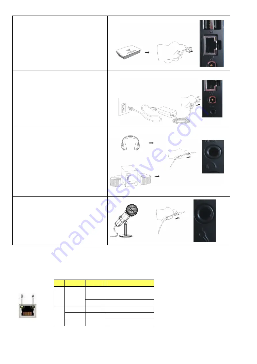
To


connect


to


the


network


Connect


the


Ethernet


cable


from


your


network


switch


/


router


to


the


RJ45


LAN


connector


found


at


the


back


of


the


unit.


To


connect


the


power


adapter


Connect


the


power


connector


from


the


supplied


power


supply


to


the


DC


In


connector


found


on


the


rear


of


the


unit


BEFORE


attaching


the


mains


power


cable


to


an


AC


outlet.


To


connect


speakers


or


headphones


Connect


the


3.5mm


audio


cable


to


the


Audio


Out


jack


found


at


the


rear


of


the


unit.


To


connect


a


microphone


or


other


audio


source


Connect


the


3.5mm


audio


cable


to


the


Line


In


jack


found


at


the


rear


of


the


unit.


Note

:


This


Mini


PC


provides


one


standard


RJ

45


jack


for


connecting


to


a


Local


Area


Network


(LAN).


Two


LEDs


are


built


into


the


RJ

45


LAN


connector.


These


LEDs


indicate


the


status


of


the


LAN.


LED  LED Color  LED state  Indicates 

A Green 

Off 

LAN link is not established 

On 

LAN link is established 

Blinking LAN 

activity 

is 

occurring 

N/A 

Off 

10 Mb/s data rate 

Green 

On 

100 Mb/s data rate 

Yellow 

On 

1000 Mb/s data rate 

Summary of Contents for EDGE-HD

Page 1: ...1 User s Manual Sapphire EDGE HD Mini PC...

Page 2: ...sions 19 3 L X 14 8 W X 2 2 H cm Weight 530g Operating System Pre installed with FREE DOS Supports Win7 Vista Important information for your safety and comfort Please read these instructions carefully...

Page 3: ...low when the hard disk is in use 3 VGA port To connect to a VGA monitor 4 HDMI port To connect to an HDMI monitor 5 Rear USB 2 0 Ports To connect to USB devices 6 LAN Port To connect to an Ethernet LA...

Page 4: ...onnector found on the rear of the unit To connect to an HDMI display TV Connect the HDMI monitor or other display device to the HDMI connector found on the rear of the unit To connect to a DVI display...

Page 5: ...dio cable to the Audio Out jack found at the rear of the unit To connect a microphone or other audio source Connect the 3 5mm audio cable to the Line In jack found at the rear of the unit Note This Mi...

Page 6: ...BIOS settings Changing some settings could damage your computer Note2 The BIOS options in this manual are for reference only BIOS screens in manuals are usually the first BIOS version when the board i...

Page 7: ...be keyed by numeric function keys Year The year can be adjusted by users System Time Allows you to set the system time The time format is hour minute second Advanced Chipset Boot Security Save Exit Ap...

Page 8: ...s CPU Configuration USB Configuration Super IO Configuration H W Monitor Onboard Device Version 2 10 1208 Copyright C 2010 American Megatrends Inc Enables or disable Boot option for legacy network dev...

Page 9: ...nfiguration Options Enabled Disabled Enable Hibernation Enables system ability to Hibernate OS S4 Sleep Sate This option may be not effective with some OS Options Enabled Disabled ACPI Sleep State Sel...

Page 10: ...d Disabled Aptio Setup Utility Copyright C 2010 American Megatrends Inc Advanced CPU Configuration Limit CPUID Maximum Disabled PSS Support Enabled PSTATE Adjustment PState 0 PPC Adjustment PState 0 N...

Page 11: ...cy USB support Disabled Keep USB devices available only for EFI application Auto Disables legacy support if no USB devices are connected USB3 0 Support Enables USB3 0 XHCI controller support Aptio Set...

Page 12: ...mand time out Options 10 sec 20 sec 30 sec 40 sec Device power up delay Maximum time the device will take before it properly reports itself to the Host controller Auto uses default values for a Root p...

Page 13: ...automatically controlled based on temperature Manual Mode 1 To set the fan speed to a constant rate the speed from 0 to 100 Manual Mode 2 This item can manual RPM count setting Aptio Setup Utility Co...

Page 14: ...les the onboard High Definition Audio controller Options Auto Enabled Disabled Aptio Setup Utility Copyright C 2010 American Megatrends Inc Advanced Marvell Gigabit LAN Enabled Wireless LAN Enabled HD...

Page 15: ...ed Boot Boot Security Save Exit Aptio Setup Utility Copyright C 2010 American Megatrends Inc Chipset North Bridge South Bridge Version 2 10 1208 Copyright C 2010 American Megatrends Inc North Bridge P...

Page 16: ...ons Enabled Disabled OnChip SATA Type Allows you to set the onboard Serial SATA type Options AHCI Legacy IDE SB USB Configuration USB Device Wakeup From S3 or S4 Allows a USB keyboard device to wake u...

Page 17: ...teractive inputs may not work properly in this mode Interrupt 19 Capture Allows specify if legacy PCI option ROMs are allowed to capture software interrupt 19h Options Enabled Disabled Boot Option 1 T...

Page 18: ...nced Chipset Boot Save Exit Aptio Setup Utility Copyright C 2010 American Megatrends Inc Security Password Description If ONLY the Administrator s password is set then this only limits access to Setup...

Page 19: ...save all current settings as user default The current setup state can later be restored using Restore User Defaults Restore User Defaults This is used to restore all tokens to settings previously stor...

Page 20: ...rous voltage points or short out parts that could result in a fire or electric shock Never spill liquid of any kind onto or into the product To avoid damage of internal components and to prevent batte...

Page 21: ...c compatibility and 2006 95 EC Low voltage directive R TTE Directive 1999 5 EC as attested by conformity with the following harmonized standard Article Safety EN60950 Article EMC EN301 489 1 17 Articl...

Page 22: ...l interference and 2 This device must accept any interference received including interference that may cause undesired operation Note The manufacturer is not responsible for ANY interference for examp...

Reviews: