background image

45

Others

Appendix

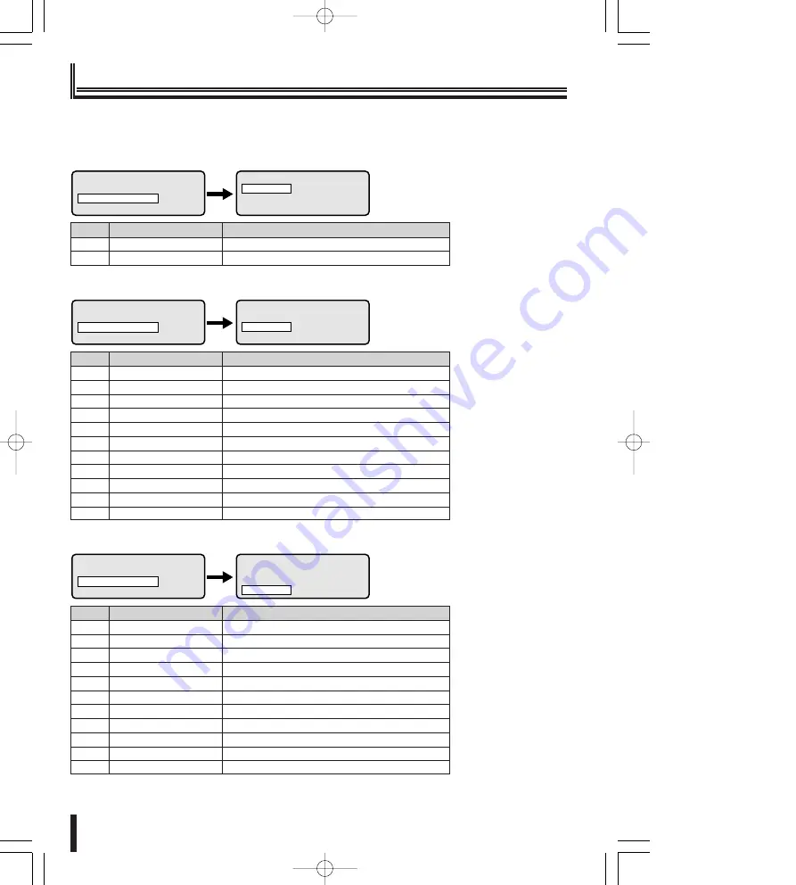
Communication table

Protocol

Communication speed (Baudrate)

1

Sanyo SSP

19200

2

---

---

Line V (Video communication)

>

LINES SETUP
 ºLine V
  Line A
  Line B

MAIN MENU
  Language: English
 ºLines Setup
  Lines Assignment

>

Protocol

Communication speed (Baudrate)

1

Video

---

2

Sanyo SSP

1200/2400/4800/9600/

19200

3

SanyoHSSP

1200/2400/4800/9600/

19200

4

Macro

1200/

9600

/19200/38400

5

Ernitec

1200/

2400

/4800/9600/19200

6

Mark Merc

2400/4800/

9600

/19200

7

Pelco D

2400

/4800/9600/19200

8

Sensorm.

1200/2400/

4800

/9600/19200

9

Vcl

1200/2400/4800/

9600

/19200

10

Videotec

1200/

9600

11

---

---

Line A (Camera communication)

LINES SETUP
  Line V
 ºLine A
  Line B

>>

MAIN MENU
  Language: English
 ºLines Setup
  Lines Assignment

Protocol

Communication speed (Baudrate)

1

Sanyo SSP

1200/2400/4800/9600/

19200

2

SanyoHSSP

1200/2400/4800/9600/

19200

3

Macro

1200/

9600

/19200/38400

4

Ernitec

1200/

2400

/4800/9600/19200

5

Mark Merc

2400/4800/

9600

/19200

6

Pelco D

2400

/4800/9600/19200

7

Sensorm.

1200/2400/

4800

/9600/19200

8

Vcl

1200/2400/4800/

9600

/19200

9

Videotec

1200/

9600

10

Video

---

11

---

---

Line B (Camera communication)

LINES SETUP
  Line V
  Line A
 ºLine B

>>

MAIN MENU
  Language: English
 ºLines Setup
  Lines Assignment

¡

The factory setting is represented in bold.

04̲L8CSD̲WA̲Misc̲GB  07.4.12 2:01 PM  ページ 45

Summary of Contents for VSP-8500

Page 1: ...00 About this manual Before installing and using this unit please read this manual carefully Be sure to keep it handy for later reference This manual gives basic connections and operating instructions GB 00 L8CSD WA Hyo1 GB 07 4 17 4 24 PM ページ 1 ...

Page 2: ...monitor when calling the address configured to the camera 31 Displaying the communications error message on the menu display 31 Sounding the warning buzzer when there is an input error 32 Configuring and adjusting the J stick 32 Adjusting the contrast of the menu display 33 Functionality test of the operating buttons 33 Initial settings 34 Operating the hard disk digital recorder 35 Address settin...

Page 3: ...not installed and used in accordance with the instructions may cause harmful interference to radio communications However there is no guarantee that interference will not occur in a particular installation If this equipment does cause harmful interference radio or television reception which can be determined by turning the equipment off and on the user is encouraged to try to correct the interfere...

Page 4: ...Do not use during thunderstorms Do not use this during thunderstorms In particular never touch the AC adapter or connection cables This can cause electric shock Do not install in unstable location The unit may fall or topple causing injuries or unit breakdowns In the event that the unit is dropped or the cabinet is broken unplug the AC adapter power plug from the outlet and contact the installer o...

Page 5: ...ion errors and unit breakdowns In direct sunlight In extreme humidity or where humidity fluctuates wildly Where water could be splashed Near heating cooling equipment or humidifiers Where cold air from air conditioners contact the unit directly Where dust is extreme Near a spark source Near magnetic objects Near explosive materials Where subject to vibration DANGER Only use with 100 to 240V power ...

Page 6: ... holes Dust and dirt on either contact portion can cause an electric short or overheating Wipe off with a dry cloth When using an outlet where humidity is high or condensation forms easily or an outlet in a kitchen or dusty environment unplug the power plug regularly and wipe off the dust and dirt adhering to the plug Never pull the power cord to unplug the power plug Always hold the power plug wh...

Page 7: ...ection can cause fires due to overheating Do not place in unstable location Place the unit in a stable location Placing the unit in an unstable location can cause injuries or unit breakdowns due to falling or toppling equipment Always Observe These Rules for Proper Use Caring for the Unit Unplug the power plug from the outlet Gently wipe away any contamination using a soft cloth When heavily soile...

Page 8: ... and Japanese can be selected Extensively control the high speed dome camera and receiver The RS485 VIDEO TELEMETRY communication line can be connected There are three security settings Password settings when starting The password input display appears when the power is turned on Password settings The password input display appears when configuring the various devices Key lock settings Licensed Un...

Page 9: ... indicate an input error P32 SANYO VSP 8500 System Controller DVR 5 CH CAM No Version information Initial screen Joystick J stick This controls the pan tilt and zoom operations of the camera The joystick is also used to select items displayed in the menu Left Right Pan Forward Back Tilt Turn Zoom DVR operating button P37 DVR Hard disk digital recorder Channel Camera button ENTER button This button...

Page 10: ... are used to set each terminal setting ON or OFF Terminal switch Camera communication terminal TELEMETRY A B Use the modular cable accessory or sold separately and the communication conversion connector included to connect to this terminal Terminal A Connects to the camera cable Terminal B Connects to the camera cable Video communication terminal VIDEO Use the modular cable included or sold separa...

Page 11: ... number of total system connections 256 units Terminal settings When multiple devices are connected by a loop to the video communication terminal and to the camera communication terminals A B of this unit data is not properly transmitted as data is reflected at both ends of the connected devices affecting other data For proper communication the terminal switch at each end of the connected devices ...

Page 12: ...O R B R B K Y L R D G R WH B L S L O R B R B K Y L R D G R WH B L S L O R B R B K Y L R D G R WH B L S L O R B R B K Y L R D G R WH B L S L O R B R B K Y L R D G R WH B L S L O R B R B K Y L R D G R WH B L S L O R B R B K Y L R D G R WH B L S L O R B R B K Y L R D G R CARD CARD MENU RESET EJECT CARD CARD MENU RESET EJECT SW ON 1 2 3 4 SW ON 1 2 3 4 SW ON 1 2 3 4 SW ON 1 2 3 4 RS 485 SETTING BAUD R...

Page 13: ...a Sanyo camera using a Sanyo DVR and directly controlling a camera P15 Using the video communication terminal and the camera communication terminal B Directly controlling a Sanyo camera P17 Using the camera communication terminal A Directly controlling a competitor s camera P19 Using the camera communication terminal A Controlling Videotec Matrix SM328S P21 Using the video communication terminal E...

Page 14: ...he protocol using the J stick right and press the ESC button LINES SETUP displays Select Line A using the J stick down and press the ENTER button LINE A displays LINE A ºProtocol Video Baudrate 6 LINES SETUP Line V ºLine A Line B 5 LINE V ºProtocol Sanyo SSP Baudrate 19200 4 LINES SETUP ºLine V Line A Line B MAIN MENU Language English ºLines Setup Lines Assignment 3 2 1 Select Video as the protoco...

Page 15: ...itor sold separately Communication conversion connector accessory A B Zoom camera sold separately Dome camera sold separately Hard disk digital recorder sold separately WH B L S L O R B R B K Y L R D G R WH B L S L O R B R B K Y L R D G R Green 2 core shielded cable Red Black Red A B White Yellow L L Connecting the communication conversion connectors Connection method 02 L8CSD WA Prep GB 07 4 12 1...

Page 16: ...ys LINE A ºProtocol Video Baudrate 6 LINES SETUP Line V ºLine A Line B 5 LINE V ºProtocol Sanyo SSP Baudrate 19200 4 LINES SETUP ºLine V Line A Line B MAIN MENU Language English ºLines Setup Lines Assignment 3 2 1 Select Video as the protocol using the J stick and press the ESC button LINES SETUP screen displays Select Line B using the J stick down and press the ENTER button LINE B screen displays...

Page 17: ...ra sold separately Dome camera sold separately Hard disk digital recorder sold separately Zoom camera sold separately Zoom camera sold separately A B Dome camera sold separately WH B L S L O R B R B K Y L R D G R WH B L S L O R B R B K Y L R D G R Green 2 core shielded cable Red Black Red A B White Yellow L L Connecting the communication conversion connectors Figure 1 WH B L S L O R B R B K Y L R ...

Page 18: ...he J stick right and press the ESC button LINES SETUP displays LINES SETUP Line V ºLine A Line B LINE V ºProtocol Baudrate 5 LINE V ºProtocol Sanyo SSP Baudrate 19200 4 MAIN MENU Language English ºLines Setup Lines Assignment LINES SETUP ºLine V Line A Line B 3 2 1 Select Line A using the J stick down and press the ENTER button LINE A displays Select Sanyo SSP as the protocol using the J stick rig...

Page 19: ...mera B SW4 OFF Video SW ON 1 2 3 4 e e e w q Monitor sold separately Communication conversion connector accessory Figure 1 Dome camera sold separately WH B L S L O R B R B K Y L R D G R White Yellow Camera B A Connecting the communication conversion connectors Figure 1 Connection method 02 L8CSD WA Prep GB 07 4 12 1 53 PM ページ 18 ...

Page 20: ... the J stick right and press the ESC button LINES SETUP displays LINES SETUP Line V ºLine A Line B LINE V ºProtocol Baudrate 5 LINE V ºProtocol Sanyo SSP Baudrate 19200 4 MAIN MENU Language English ºLines Setup Lines Assignment LINES SETUP ºLine V Line A Line B 3 2 1 Select Line A using the J stick down and press the ENTER button LINE A displays Select Example Pelco D as the protocol using the J s...

Page 21: ...F Camera B SW4 OFF Video SW ON 1 2 3 4 e e e w q Competitor s camera Monitor sold separately Communication conversion connector accessory Figure 1 WH B L S L O R B R B K Y L R D G R White Yellow Camera B A Connecting the communication conversion connectors Figure 1 Connection method 02 L8CSD WA Prep GB 07 4 12 1 53 PM ページ 20 ...

Page 22: ... 0 None MENU Mark Position 5 LINE ASSIGNMENT ºDVR CAMERAS ASSIGNMENT RESET 4 MAIN MENU Language English Lines Setup ºLines Assignment 3 2 1 The camera cannot be operated through the Matrix SM328S Press the DVR button enter the DVR address i e 99 using the numeric buttons and press the ENTER button The connection to the Matrix SM328S is complete Press the numeric button 1 while pressing the SET but...

Page 23: ...t right Numeric buttons 1 0 can be entered buttons CLEAR ENTER Menu selection Refer to the Matrix SM328S Instruction Manual for details regarding operation 3 ON 1 2 3 4 e e e SW ON 1 2 3 4 Terminal settings SW1 OFF fixed SW2 OFF Camera A SW3 OFF Camera B SW4 ON Video w q Camera Monitor AC adapter accessory Communication conversion connector accessory A B Connection method WH B L S L O R B R B K Y ...

Page 24: ...ssignment LINES SETUP ºLine V Line A Line B Device assignment settings P25 Unit address settings P27 Password settings P28 Other function settings P30 LINE ASSIGNMENT ºDVR CAMERAS ASSIGNMENT RESET KEYBOARD ID NUMBER Number 0 4 Initial settings P34 2 3 4 5 6 7 REVERT TO DEFAULT CONFIGURATION MENU Yes ESC No PASSWORD CHANGE ºPower On Pwd Setup Pwd Key Lock On Pwd Language settings P24 1 LANGUAGE Fra...

Page 25: ... other lines using the same steps 4 3 LINE V ºProtocol Sanyo SSP Baudrate 19200 LINE A ºProtocol Video Baudrate LINE B ºProtocol Sanyo SSP Baudrate 19200 2 MAIN MENU Language English ºLines Setup Lines Assignment LINES SETUP ºLine V Line A Line B 1 1 Language settings Press the MENU button MAIN MENU displays Select Language using the J stick up down and press the ENTER button Select a language usi...

Page 26: ...ers Communication line settings Press 0 or 1 using the numeric buttons 0 Displays Not Used 1 Displays Line V Simultaneously changing the assigned DVR to the same line Example Collectively changes the DVR s 3 to 9 Line V to Not used Only sequential settings can be configured Select the first DVR number i e 3 to configure to Line V using the J stick and press the MENU button The bottom of the displa...

Page 27: ...DVR 2 Channel 6 ENTER to modify CAMERA NUMBER Line Phys Adr DVR Channel ENTER to modify Enter the Channel i e 7 using the numeric buttons and press the ENTER button address 1 16 Use the ENTER button to move the cursor to the items to change Press the ESC button LINE ASSIGNMENT displays Press the ESC button repeatedly and appear the initial display Simultaneously changing the assigned cameras to th...

Page 28: ... i e 8 of Line B using the J stick and select using the numeric buttons i e 2 Collectively changes camera 3 to 8 to Line B Confirmation When the CAMERA NUMBER is set to 3 using the J stick up down the number becomes Line B When the CAMERA NUMBER is set to 9 the number becomes Line A The collective changes of the lines can be confirmed CAMERA NUMBER 8 Line B Phys Adr 8 DVR 1 Channel 8 ENTER to modi...

Page 29: ...t configured When a password is set a screen requesting the password appears when the power is turned on Enter the configured password When the wrong password is entered WRONG PASSWORD displays Enter the correct password Password registration when power is turned on Select Power On Pwd using the J stick up down and press the ENTER button POWER ON PASSWORD displays Enter the password using the nume...

Page 30: ...6 PASSWORD CHANGED PASSWORD CHANGE Power On Pwd ºSetup Pwd Key Lock On Pwd B Password registration to key lock the operating buttons Select Key Lock On Pwd using the J stick up down and press the ENTER button KEY LOCK ON PASSWORD displays Enter the password using the numeric buttons i e 123456 and press the ENTER button PASSWORD CHANGED blinks for about 3 seconds and the entered password is record...

Page 31: ...ions exist to ensure the smooth operation of this unit This function automatically switches the camera image connected to the DVR to the DVR s main monitor when calling the address configured to the camera P31 This function displays the communications error message on the menu display P31 This function configures a warning buzzer when there is an input error P32 This function configures and adjust...

Page 32: ...dr Lnk ºCom Error Display Buzzer B Automatically switching the camera image connected to the DVR to the DVR s main monitor when calling the address configured to the camera Select Other Parameters using the J stick up down and press the ENTER button OTHER PARAMETERS displays Select Direct Cam Adr Lnk using the J stick up down and press the ENTER button DIRECT CAM ADR LINK displays J stick right ON...

Page 33: ...STICK CALIBRAT 3 Z 0377 Z0693 Z 0693 Enter to end JOYSTICK CALIBRAT 2 X 0423 X0423 X 0521 Y 0531 Y0569 Y 0598 Enter to end JOYSTICK CALIBRAT 2 Move the joy on the corners JOYSTICK CALIBRAT 1 Release the joy and press Enter to continue OTHER PARAMETERS Com Error Display Buzzer ºJoystick Calibrat D Sounding the warning buzzer when there is an input error Select Other Parameters using the J stick up ...

Page 34: ... ZOOM BACK MAX t NF FOCUS NEAR FAR y OC IRIS OPEN CLOSE u M MENU i M DVR o C CH CAM 0 2 SHIFT Release all keys to begin the test Press SHIFT SET END to exit EC12345 123 MM CXHGIF 456 C 2 PSTM NF 789 S S BZ OC 0 CE E Functionality test display OTHER PARAMETERS Joystick Calibrat Display Contrast ºKey Test F Adjusting the contrast of the menu display Select Other Parameters using the J stick up down ...

Page 35: ... RESET 2 REVERT TO DEFAULT CONFIGURATION MENU Yes ESC No MAIN MENU Passwords Other Parameters ºReset Keyboard 1 1 S SEQ 2 S SET 3 C CLEAR 4 E ENTER 5 E END Press the operating button to test Correct operation The symbol or number of the button changes to a black dot Incorrect operation The symbol or number does not change Ending and canceling Press the SHIFT SET and END buttons at the same time 45...

Page 36: ...e camera number Refer to Camera assignment and communication line settings P26 B DVR 4 CH 1 CAM No 49 Selected device Operable cameras DVR1 1 CH1 16 CH16 DVR2 17 CH1 32 CH16 DVR3 33 CH1 48 CH16 DVR4 49 CH1 64 CH16 DVR5 65 CH1 80 CH16 DVR6 81 CH1 96 CH16 DVR7 97 CH1 112 CH16 DVR8 113 CH1 127 CH15 Press the DVR button All the numbers disappear and the operating DVR can be selected Select the operati...

Page 37: ... DVR 1 CH CAM No DVR 1 CH CAM No DVR 1 CH 4 CAM No DVR menu settings Press the MENU button while pressing the SET button The DVR main menu displays in the monitor Select the menu using the J stick up down while pressing the SET button and set to J stick right The sub screen displays Set to J stick left when returning to the previous screen Press the ESC button while pressing the SET button to end ...

Page 38: ...ected command The initial display disappears in about 2 seconds 1 Play 2 Stll 3 Stop 4 RevP 5 Plus 6 FF 7 Mult 8 Quad 9 Rec 0 RecStop Figure 1 DVR 1 CH 1 CAM No 1 PLAY A Operations using SET button combinations P39 Press the 1 0 or button while pressing the SET button The command of the pressed button appears at the bottom of the initial display and the operating mode switches to the selected comm...

Page 39: ...ayback speed when pressed during playback PLUS Plus PLUS screen displays FAST FORWARD FF This fast forwards the image during playback This increases the playback speed when pressed during playback This decreases the playback speed when pressed during playback MULTI Mult The main monitor screen can be divided into 6 9 and 16 screens The divided display differs based on the number of camera input te...

Page 40: ... change the item using the J stick while pressing the SET button Press the SEARCH EXIT button while pressing the SET again to exit 1 Main 2 Monitor2 4 ª 5 6 º 7 PrvAl 8 Src 9 NxtA Copy 0 SLOn NEXT ALARM NxtA Press this button during playback or pause This plays back the next alarm image COPY EXIT Copy The image recorded to the normal recorded area or alarm recording area can be copied to a backup ...

Page 41: ... is connected to the DVR The camera can be called from both the channel and number A 1 Calling from the channel Press the CH CAM button The selected channel camera number disappears and the cursor in the CH line blinks Enter the channel of the camera i e 5 to view using the numeric buttons and press the ENTER button The image on the monitor screen switches to camera 5 A 2 Calling from the camera n...

Page 42: ...the CODE and press the ENTER button AUX 1 ON This function transmits the ON command to AUX1 For example if this button is pressed AUX 1 ON displays and in the case of Sanyo s Day Night camera the camera automatically switches to color mode c CAMERA FUNCTION CODE 1 9999 AUX 2 ON This function transmits the ON command to AUX2 For example if this button is pressed AUX 2 ON displays and in the case of...

Page 43: ...ess the button for one touch focus AUTO PAN START This function starts the auto pan The auto pan stops when another operation is started SEQUENCE START The sequential pan automatically starts using a preset position The sequential pan stops when another operation is started c c c GO TO PRESET POSITION 1 255 Press ESC to return c AUXILIARY CONTACT AUX ON 1 16 Press ESC to return c TOUR START This f...

Page 44: ... on the selected numeric button PAN PATTERN 2 1 4 Press ESC to return 2 1 sSequence Selection 1 4 Press the SEQ button while pressing the SHIFT button SEQ PATTERN menu displays Press a numeric button i e 3 and press the ENTER button The sequence operates according to the recorded operation on the selected numeric button sTour Selection 1 4 Press the TOUR button while pressing the SHIFT button TOUR...

Page 45: ...m RS485 42 buttons Three axis joystick pan tilt zoom RJ 11 terminal VIDEOx1 TELEMETRYx2 RS 232C D SUB 9 pin terminal Normal mode PC mode 1 bit dipswitch Terminate 3 bit dipswitch Video Telemetry A B 2400 4800 9600 19200 bps Total 256 units Controller 5 units Hard disk digital recorder 98 units total PTZ camera CCD camera TELEMETRY A 127 units TELEMETRY B 127 units Matrix switch Videotec SM328S 1 u...

Page 46: ... 2400 4800 9600 19200 10 Videotec 1200 9600 11 Line A Camera communication LINES SETUP Line V ºLine A Line B MAIN MENU Language English ºLines Setup Lines Assignment Protocol Communication speed Baudrate 1 Sanyo SSP 1200 2400 4800 9600 19200 2 SanyoHSSP 1200 2400 4800 9600 19200 3 Macro 1200 9600 19200 38400 4 Ernitec 1200 2400 4800 9600 19200 5 Mark Merc 2400 4800 9600 19200 6 Pelco D 2400 4800 9...

Page 47: ...g time in seconds upon reaching specified position Example 1000 Deletes previously defined order 1001 Writes preset position 1 into order 1005 Writes preset position 5 into order 1006 Writes preset position 6 into order 2005 Deletes preset position 5 Dome cameras can be set to automatically move to the return position after a set stopping time passes XX 01 99 Return position Cannot select position...

Page 48: ...era Decreases the camera integration level decreases shutter speed Increases the camera integration level increases shutter speed Zero lux ON infrared filter OFF Zero lux OFF infrared filter ON Switch level Brighter Initial setting value Darker All zones ON All zones OFF Switches zone specific cursor ON OFF Switches masking ON OFF depending on cursor status Cursor ON This code enables placing a sm...

Page 49: ...g for 5 minutes XX 05 200 Automatic stop OFF XX 00 Dome cameras can be set to automatically start the specified patrol order after a set stopping time passes XX 01 99 Waiting time minutes before automatic patrolling Y 0 5 Patrol number when waiting time XX 00 the function is invalid Example 1153 After stopping for 15 minutes XX 15 automatically patrols in No 3 Y 3 patrol order 1003 Automatic patro...

Page 50: ... value X 1 7 Speed number Values can be allocated X 1 7 Dome camera operation test at No X uniform speed To stop the test move the joystick Example 8007 Speed value equal to 7 X 007 9001 The 7 speed value is allocated to Speed No 1 X 1 Writes speed value into speed No 2 3 4 5 6 etc 8138 138 X 138 speed value 9007 Allocates speed value 138 to speed No 7 X 7 To test speed No 7 next 9107 Dome camera ...

Page 51: ...s screen Initializes remote camera operations pan tilt Initializes remote camera operations to default values Backlight compensation ON Backlight compensation OFF White balance ON White balance OFF Makes unit phase delay mode valid X 1 8 Zoom speed X 1 8 Focus speed Shutter speed Line lock level White balance R B adjustment White balance M G adjustment Gain Auto iris level Auto iris vertex 04 L8CS...

Page 52: ... invalid 134 Makes only relays 1 3 and 4 valid Relay 2 is invalid Begins collection pattern 1 Begins collection pattern 2 Begins collection pattern 3 Checks new pattern and replaces the previous definition Ends pattern collection Begins pattern 1 Begins pattern 2 Begins pattern 3 Deletes pattern 1 Deletes pattern 2 Deletes pattern 3 Example Definition of Pattern 2 72 Deletes old pattern 2 relates ...

Page 53: ...ies Sanyo camera AUX command table Switches the Day Night camera to color mode Switches the Day Night camera to black and white mode Switches the Day Night camera to Day Night auto mode Refer to the operating manual regarding explanations of the Auto Return function Exclusively for Pelco D All cameras can receive commands and operate using address 99 Enabled only when alarm output 2 is set to REMO...

Page 54: ...PRESET Goto Preset 1 255 Go to Preset 1 250 Goto Preset 0 127 Goto Preset 1 128 1 IRIS CENTER Yes IriD 2 AUTO FOCUS ON Yes Afo Yes Yes 3 PAN Autopan Start Autopan Start Apa Autopan Start Yes SHIFT PAN Pan pattern 1 4 4 SEQ Sequence Start Patrol Std Start Pat SHIFT SEQ Seq pattern 1 4 Patrol Std Set menu 5 TOUR Tour Start Patrol S A Start PaV Tour Start 1 4 Patrol Start SHIFT TOUR Tour Pattern 1 4 ...

Page 55: ...et 1 250 Goto Preset 1 254 Goto Preset 0 95 Goto Preset 1 127 1 IRIS CENTER 2 AUTO FOCUS ON Yes Yes 3 PAN Pattern Start Pattern 1 Start Autopan Toggle SHIFT PAN Pattern Definition Start Autopan Start 4 SEQ Pattern 2 Start Patrol Std Start SHIFT SEQ Patrol Std Set menu 5 TOUR Pattern 3 Start Patrol S A Start SHIFT TOUR Patrol S A Set menu 6 PRESET MEMORY Preset Mem 1 250 Preset Mem 1 254 Preset Mem...

Page 56: ...Printed on recycled paper 1AC6P1P3169 L8CSD WA 0407KR VT SANYO Electric Co Ltd Printed in Italy 04 L8CSD WA Misc GB 07 4 12 2 01 PM ページ 55 ...

Reviews: