Sanyo VSE-2300 Series Instruction Manual Download Page 9

6.8

Lens Wiring

WARNING: Only use the cables specified
under "INSTALLATION, Cable Requirements"
for wiring of the lens.

1. Install the last 1/2-inch NPT fitting into the remaining hole

in the rear cap. Zoom lenses can only be installed into 
VSE-2400 housings.

2. If installing a zoom lens, insert the lens control cable

through the last fitting at the rear of the housing. Attach
the lens wiring to the lens mating connector and connect
it to the lens. If mating connector is not available, connect
directly to the lens cable. Pull any excess wire out of the
housing and tighten the fitting to 8.5 N

.

m to 9.0 N

.

m

(75 in

.

lb to 80 in

.

lb). This torque rating is approximately 1

to 1-1/2 turns past the point where the fitting starts to
grip the wire. Failure to do so will result in water damage
to all electronic parts.

NOTE: See specification on lens cord for correct plug
connection.

Be sure to securely tighten all fittings to
ensure a liquid-tight seal. Failure to do so
could allow water to enter the housing and
damage the camera and lens.

3. If using a pan/tilt with a feed-through cable, insert

the camera/lens function cable in through the left fitting at
the rear of the cradle. Wire the functions as described
above or as needed.

Use of "drip loops" is recommended on the
wiring outside of the rear end cap.

6.9

Camera/Lens Adjustment

Verify camera and lens operation before final assembly of the
cradle into the housing. Adjust the camera focus and iris as
necessary. See individual camera instructions.

6.10 Final Assembly
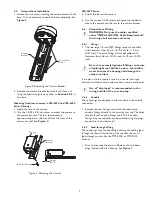
1. Use the plugs or fittings provided to plug any remaining

holes in the rear cap.

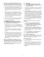
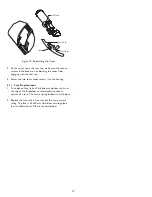
2. Reinstall the cover. Align the bottom of the cover ribs

with the top of the base. Slide the cover onto the base.
Make sure the seal is not folded over or torn. Use
silicone grease to lubricate the seals if necessary. See
Figure 10
.

Be sure to securely tighten all fittings to ensure a
liquid-tight seal. Failure to do so could allow water to
enter the housing and damage the camera and lens.

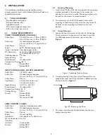
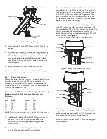
6. Connect the supply power wires to the left side or the

top side of the terminal block provided. Strip no less than
6 mm (0.25-inch) and no more than 8 mm (0.31-inch) of
insulation away from the wire. Be sure not to nick the
wires.

7. Cut the camera power cord, leaving enough cable to

allow connection to the terminal block. Strip no less than
6 mm (0.25-inch) and no more than 8 mm (0.31-inch) of
insulation away from the wire. Be sure not to nick the
wires.  Connect these wires to the left side or the top
side of the terminal block.

8. On heater and heater/blower units, make sure the heater

and fan wires stay connected to the terminal block.

6.7

Video Coax Connection

WARNING: Only use the cables specified under

"INSTALLATION, Cable Requirements" for
wiring of the video coax connection.

1. For VSE-2300 versions, install a 1/2-inch NPT fitting into

the remaining hole in the rear cap. For VSE-2400 versions,
install a 3/8-inch NPT fitting through the center small hole
of the rear cap.

2. Route the video coax cable through one of the fittings

installed in step 1 or one of the feed-through fittings in
the base.

3. Attach BNC connector to the coax and connect it to the

camera. Pull any excess wire out of the housing and
tighten the fitting to 8.5 N

.

m to 9.0 N

.

m (75 in

.

lb to 80

in

.

lb). This torque rating is approximately 1 to 1-1/2 turns

past the point where the fitting starts to grip the wire.
Failure to do so will result in water damage to all
electronic parts.

Be sure to securely tighten all fittings to ensure a
liquid-tight seal. Failure to do so could allow water to
enter the housing and damage the camera and lens.

Use of "drip loops" is recommended on the wiring
outside of the rear end cap.

9

Summary of Contents for VSE-2300 Series

Page 1: ...E 2400 SERIES INSTRUCTION MANUAL Cylindrical Environmental Camera Housings About this manual Before installing and using this unit please read this manual carefully Be sure to keep it available for later reference ...

Page 2: ...lar attention to cords and plugs convenience receptacles and the point where they exit from the appliance 12 Power Lines An outdoor system should not be located in the vicinity of overhead power lines or other electric light or power circuits or where it can fall into such power lines or circuits When installing an outdoor system extreme care should be taken to keep from touching such power lines ...

Page 3: ...nug ist um einen elektrischen Schlag zu verursachen Das Ausrufezeichen im gleichseitigen Dreieck soll den Benutzer auf wichtige Bedienungs und Wartungsanleitungen in der dem Gerät beigefügten Literatur aufmerksam machen PRECAUCIONES DE SEGURIDAD Debido a limitaciones de espacio esta etiqueta puede aparecer en la parte inferior de la unidad El símbolo representado por un relámpago con punta de flec...

Page 4: ...Accessibility Feed through Wiring Option through the Mounting Base Liquid Tight Fittings on Rear of Housing Multiple Mounting Configurations Available Available with Preinstalled Heater or a Preinstalled Heater Blower Heater Blower Combination Minimizes fogging and Extends Temperature Limits NEMA 4 and IP65 Weatherproofing Standards 1 UNPACKING Unpack carefully This is mechanical equipment and sho...

Page 5: ... For VSE 2300 Series housings VSE SS2400 For VSE 2400 Series housings MOUNTS MTS 2000 Mount Wall Mount Feed through mount attached to the foot of housing for VSE 2300 VSE 2400 Series housings MTS 2030 J mount Feed through J mount for VSE 2300 VSE 2400 Series housings allows housing to be mounted from ceiling MTS 2040 Pole Mount Adapter For use with MTS 2000 Wall Mount MTS 2050 Pedestal Mount 8 inc...

Page 6: ... TOOLS REQUIRED Small flat blade screwdriver Phillips screwdriver P2 Adjustable wrench Wire cutter stripper crimper tool 5 32 in or 4 mm hex wrench 6 2 CABLE REQUIREMENTS VIDEO TRANSMISSION COAXIAL Cable Type RG 59 U for runs 300 m 1000 ft RG 11 U for runs 600 m 2000 ft Cable Size Outside diameter between 4 6 mm 0 181 in 7 9 mm 0 312 in Cable Shape Round Shield 93 Braided copper shield Center Cond...

Page 7: ...ttings 1 The two large 1 2 inch NPT fittings accept round cable with diameters from 4 3 mm 0 17 inch to 11 9 mm 0 47 inch The small fittings will accept cables with diameters from 4 6 mm 0 181 inch to 7 9 mm 0 312 inch Be sure to securely tighten all fittings to ensure a liquid tight seal Failure to do so could allow water to enter the housing and damage the camera and lens If a sealant is to be u...

Page 8: ...oximately 1 to 1 1 2 turns past the point where the fitting starts to grip the wire Failure to do so will result in water damage to all electronic parts 4 Attach the foot to the top bracket of the mount 5 Cover the holes in the rear cap with the rubber plugs provided Push in until flush and then release 6 6 4 Power Connections Power connection into the housings is to be supplied through a minimum ...

Page 9: ...folded over or torn Use silicone grease to lubricate the seals if necessary See Figure 10 Be sure to securely tighten all fittings to ensure a liquid tight seal Failure to do so could allow water to enter the housing and damage the camera and lens 6 Connect the supply power wires to the left side or the top side of the terminal block provided Strip no less than 6 mm 0 25 inch and no more than 8 mm...

Page 10: ... cap 4 Screw the two rear captive screws into the housing 6 11 Fuse Replacement 1 To replace a fuse take a flat blade screwdriver and twist the top of the fuseholder counterclockwise about a quarter of a turn The fuse is spring loaded so it will eject 2 Replace the fuse with a fuse that has the same current rating The fuse is a 5x20 mm slow blow cartridge type fuse Littelfuse Series 218 are recomm...

Page 11: ... party to assume for it any other obligation or liability SFC DISCLAIMS ALL OTHER WARRANTIES EXPRESS OR IMPLIED WITH REGARD TO THIS PRODUCT INCLUDING THE WARRANTIES OF MERCHANTABILITY AND FITNESS IN NO EVENT SHALL SFC BE LIABLE FOR ANY SPECIAL INCIDENTAL OR CONSEQUENTIAL DAMAGES ARISING FROM THE OWNERSHIP OR USE OF THIS PRODUCT OR FOR ANY DELAY IN THE PERFORMANCE OF ITS OBLIGATIONS UNDER THIS WARR...

Page 12: ...Sanyo Fisher Company Security Video Division 21605 Plummer Street Chatsworth CA 91311 Tel 818 998 7322 Fax 818 717 2716 Technical Support 888 66SANYO Printed in USA 100 0004 001 SAN 6 02 ...

Reviews: