1AC6P1P3087--
L5BL2/XE (0606KP-SY)
调整摄像机
b
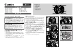
遥控设置摄像机
建议使用单独订购的摄像机控制器
(VAC-70)
设置和调整此摄像机。
摄像机控制器使您可以调整摄像机的
角度 (摇摆度
/
倾斜度)和在主菜单中执行高级设定。有关详细信息,请参见摄像机控制器的使用手册。
b
安装附件
一旦您结束设置
/
调整,请记得将摄像机控制器断开。
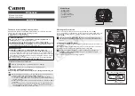
在便携式监视器上检查设定屏幕和摄像机的角度
使用带鳄鱼夹的电缆将电路板上的
MONITOR OUT
引脚和
GND
引
脚连接到监视器。结束检查之后,请记得查取下电缆。
有一个专用的
MONITOR OUT
接头提供给便携式监视器使用。
b
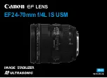
检查设定屏幕并做出更改
1)
按住
SET
按钮 (
1
)约一秒以上。
主菜单就会出现。
2)
上下按 “选择”按钮 (
2
)选择一个菜单,然后按下
SET
按钮。
3)
左右按下 “选择”按钮选择设置项和值,然后按下
SET
按钮。
b
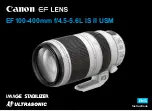
检查摄像机角度并做出更改
1)
在实况模式下上、下、左、右按 “选择”按钮 (没有显示菜单)。
您可以设置摄像机的角度 (摇摆度:
d
或
c
/
倾斜度:
j
或
l
)。
2)
按下
SET
按钮,然后左右按下 “选择”按钮。
您可以设置变焦 (广角:
d
/
伸缩:
c
)。
•
每次按下
SET
按钮时,就可以在摇摆度
/
倾斜度和变焦之间切
换进行中的操作。
VIDEO OUT CAMERA
DC IN 3V
Ð +
VAC-70
视频输入
BNC
类型
RG-6U
同轴电缆
300 m
或以下
UP
DOWN
LEFT
RIGHT
SET
GND
MONITOR
OUT
1
2
1
六角扳手
(大、小):各一个
2
垫片
3
机盖片
4
卡榫屏蔽环
Printed on recycled paper
Imprimé sur du papier recyclé
Gedruckt auf Recyclingpapier
使用再生纸印刷
SANYO Electric Co., Ltd.
Printed in Japan
L5BL2_XE(INSTALLATION).book 7 ページ 2006年6月23日 金曜日 午後7時9分