


4
3
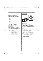
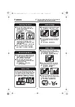
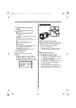
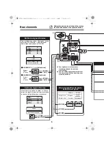
System terminals (Push-lock)
Used to connect external system control
devices.
1
RS-485 control terminals (Push-lock)
Used to perform remote operations of the
camera.
Connect these terminals to a communication
device such as system controller.
2
COM terminal (earth terminal)
3
UTP terminals
Used to output video signal using a UTP
(Unshielded Twist Pair cable).
Connect these terminals to the NVT receiver.
4
AC24V/DC12V terminal
Inputs the power.
Connect this terminal to the power supply.
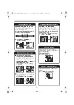
• When the camera is turned on, the POWER
lamp lights and the system information of the
camera is displayed on the startup screen for
about 10 seconds.
b
For zoom/focus
While viewing the live image, you can perform
focusing or zooming operation.
1
c
: Wide
d
: Tele
j
: Near
l
: Far
2
Pressing the button once starts auto-focus
function.
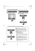
b
For menu operations
1
j
: Moves the cursor upward.
l
: Moves the cursor downward.
c
: Changes the setting value or moves the
cursor to the right.
d
: Changes the setting value or moves the
cursor to the left.
2
Pressing and holding the button for about
3 seconds displays the main menu.
While performing menu operations, the
button may be used to switch the menu
screen to the next one.
CAMERA VER
PROTOCOL
ADDRESS
X.XX-XX
XXXX
X
SET
1
2
Side panel
L5CB2_XE(INSTALLATION).book 4 ページ 2008年1月23日 水曜日 午後1時38分