


Alarm Settings
Recording New Alarm Data
If recording new alarm data into the camera’s
internal memory, you should delete the old data
that is recorded in the memory. This will free up
memory space so that the new alarm data can
be recorded. (p. 48)
Note:
•
If an expansion memory card (CF) is
installed, the alarm data will first be recorded
into the camera’s internal memory, and then
it will be automatically transferred to the
memory card. This is useful for times when
you want to record more than one alarm
event.
•
The alarm data in the internal memory can
be saved into a computer as still images.
Furthermore, the data can also be
downloaded as continuous images.
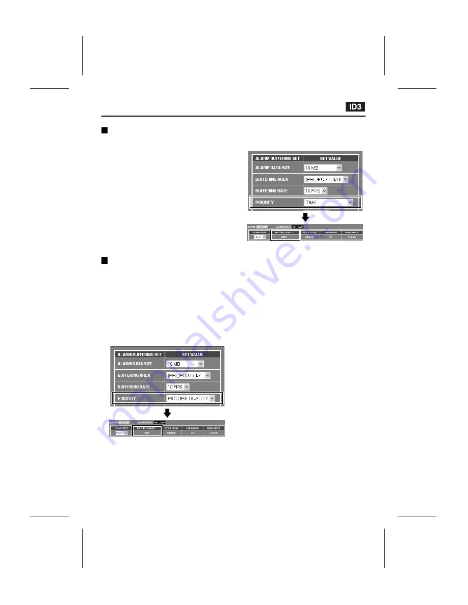
Fixed Settings During
Pre/Post-Alarm Recording
If the pre-alarm/post-alarm recording area ratio
is set to something from 1/9 to 5/5 so that
pre-alarm recording can be carried out, the
transmission settings (PICTURE QUALITY,
RESOLUTION and IMAGE MODE (COLOR))
are fixed.
Example 1: If “PRIORITY” is set to “PICTURE
QUALITY”
The image quality during pre- and post-alarm
recording will be fixed at “HIGH”.
Example 2: If “PRIORITY” is set to “TIME”
The image quality during pre- and post-alarm
recording will be fixed at “MID1”.
When alarm data is recorded into the camera’s
internal memory, the settings that are fixed
during pre- and post-alarm recording will be
canceled. However, if a memory card is inserted,
the settings will be fixed until the recording area
becomes full.
L5AM2/US (VCC-WB4000) GB 2003, 6, 6
English
– 41 –


