-
11
-
3-10. Y-Gain Adjustment
Adjustment location:
Computer screen
Measuring location:
CN204 pin6 (VIDEO OUT)
Measuring equipment:
Oscilloscope
Subject:
Gray scale chart
Adjusting method:
1. Display the gray scale chart at designated picture angle.
2. Use the “ ” button to be F LOCK in the adjustment
window.
3. Click the LOCK button.
4. Use the “ ” button to be YGAIN in the adjustment
window.
5. Shield light with a lens cap to provide dark condition.
6. Use the computer’s mouse to adjust the YGAIN in the
adjustment window so that the video out terminal is 700 ±
10 mVp-p.
3-11. Hue and Chroma Adjustment
Adjustment location:
Computer screen
Measuring location:
CN204 pin6 (VIDEO OUT)
Measuring equipment:
Oscilloscope, vectorscope
Subject:
Color bar chart
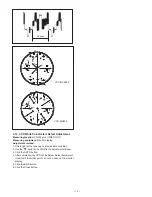
1. Use the “ ” button to be R GAIN in the adjustment window.
2. Display the color bar chart at designated picture angle.
3. Shield light with a lens cap to provide dark condition.
4. Select the R GAIN and B GAIN by using the “ ” and “ ”
button in the adjustment window.Adjust by operating level
scroll bar so that the red and yellow luminescent spots are
the size and position which are designated in the vectorscope.
5. Select the R HUE and B HUE by using the “ ” and “ ”
button in the adjustment window. Adjust by operating level
scroll bar so that the red and yellow luminescent spots are
the size and position which are designated in the vectorscope.
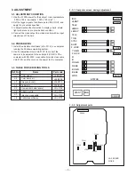
3-7. Frequency Adjustment (INT)
Adjustment location:
CT252, CT202 (CA-2)
Measuring location:
TP203, TP202 (CA-2)
Measuring equipment:
Frequency counter, Digital voltmeter
Subject:
No designation
Adjusting method:
1. Adjust with CT252 so that the frequency of TP203 is
17734475 Hz ± 50 Hz (VCC-MC600P) or 14318180 Hz ±
50 Hz (VCC-MC600).
2. Adjust with CT202 so that the voltage of TP202 is 7.0 V ±
0.5 V (VCC-MC600P only).
3-8. Frequency Adjustment (L-L)
Adjustment location:
CT201 (CA-2)
Measuring location:
TP201 (CA-2)
Measuring equipment:
Digital voltmeter
Subject:
No designation
Adjusting method:
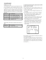
1. Use the “ ” button to select the TRIG in the frequency
adjustment window.
2. Input a pulse signal to the pin 8 of CN204.
3. Adjust with CT201 so that the voltage of TP201 is 7.0 V ±
0.5 V.
3-9. SYNC and BURST Level Adjustment
Adjustment location:
Computer screen
Measuring location:
CN204 pin6 (VIDEO OUT)
Measuring equipment:
Oscilloscope
Subject:
Adjusting method:
1. Shield light with a lens cap to provide dark condition.
2. Use the “ ” button to be SYNC in the adjustment window.
3. Use the computer’s mouse to adjust the SYNC in the
adjustment window so that the video out terminal is 300 ± 5
mVp-p (VCC-MC600P) or 286 ± 5 mVp-p (VCC-MC600).
4. Use the “ ” button to be BURST in the adjustment
window.
5. Use the computer’s mouse to adjust the BURST in the
adjustment window so that the video out terminal is 300 ±
5 mVp-p (VCC-MC600P) or 286 ± 5 mVp-p (VCC-MC600).
50Hz ± 0.25Hz (VCC-MC600P)
60Hz ± 0.25Hz (VCC-MC600)
5V
PULSE SIGNAL
VIDEO OUT
300 mV ± 5 mV
or
286 mV ± 5 mV
sync
burst
300 mV ± 5 mV
or
286 mV ± 5 mV
VIDEO OUTPUT
700 mV ± 10 mV
35 µsec

