
Français
Español
English
B
A
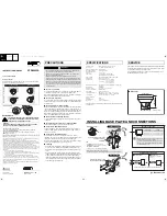
INSTALLATION
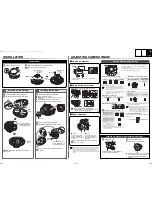
ADJUSTING CAMERA IMAGE
Preparation
1
Remove the dome cover.
Push
Installing on the Ceiling
1
Connect the cables from the ceiling.
2
Mount the camera unit to the base plate.
Make sure that the camera unit and base plate fit
perfectly.
2
1
Supplied
screw
Push the camera unit
until it clicks taking care
not to pinch the cable.
Power
cables
1
Set the lens in the correct direction.
1
Remove the black screw
A
.
2
Turn the lens in the arrow direction to reverse the
orientation.
3
Confirm that the dials are located at the top.
4
Temporarily tighten the removed black screw
A
.
2
Connect the cables from the wall.
3
Mount the camera unit to the base plate.
Make sure that the camera unit and base plate fit
perfectly.
14
2
3
A
Black screw
3
2
Supplied
screw
Push the camera unit
until it clicks taking care
not to pinch the cable.
Installing on the Wall
b
Checks on monitor
Connect a portable monitor.
A dedicated MONITOR OUT connector is provided for
portable monitor.
GND
MONITOR
OUT
b
Angle-of-view adjustment
Adjust the angle of view by moving the lens unit.
●
Do not touch the lens and lens barrel.
●
When rotating the lens unit, make sure a metal
edge does not damage the cables.
200
(Ceiling Installed)
(Wall Installed)
b
Zoom and focus
When finished, tighten the zoom and focus ring
knobs
AC
securely.
1
Zoom
Loosen the zoom ring
knob
A
, and turn the
zoom ring
B
to zoom in
or out.
2
Focus
Loosen the focus ring
knob
C
, and turn the
focus ring
D
to focus on
the object.
D C
A
B
When monitoring lighting or other extremely bright objects (which
exceed the maximum required illumination), smearing may occur in
the vertical or horizontal direction (either above and below the
high-brightness object or as a perpendicular band). In such a case,
adjust the angle of illumination and other factors while observing the
monitor.
Camera adjustments/settings
The camera comes pre-adjusted and ready to install at the
time of factory shipment, but you can make adjustments or
settings if you need.
If you have trouble adjusting the camera, consult your dealer
or an Authorized Sanyo Service Center.
●
Electronic shutter speed setting
(unit: second)
Switch1: MSB
Switch2: LSB
●
Aperture compensation
●
Backlight compensation
Only when using an auto-iris lens
* If the background of the object is extremely dark, set to
Center zone metering.
●
White balance (color compensation)
●
Sync setting
* Adjust the roll by turning the LINE PHASE dial on the
second and subsequent cameras.
●
Lens iris level adjustment
If the entire image is too dark or too bright, adjust
the condition.
1/60
1/100
1/1000
1/2000
• Using the high speed electronic shutter indoors
with low lighting, will give darker pictures. In
such a case, add some lights to make sure the
lighting is sufficient.
• If the lighting is very bright, pay attention to the
light angle in order to avoid or minimize the
smear phenomenon effect.
Sharp outline
Normal outline
Multi-spot metering
Backlight compensation
to the entire screen*
High
Normal
Center zone metering
Backlight compensation
to the central portion of
the screen
OFF
2
1
2
1
2
1
2
1
3
3
5
4
5
4
5
4
5
4
Manual White Balance
Auto-Tracing
White balance
(ATW)
Line-Lock
Synchronizes the unit with
power frequency*
Internal sync
If the vertical roll cannot be corrected by adjusting
the LINE PHASE dial on the second and
subsequent cameras, try adjusting the LINE
PHASE dial on the first camera. If it still cannot be
corrected, please check that the polarity of the
power cords of all connected devices is correct.
Low (darker)
High (brighter)
RED
BLUE
6
MWB
Turn clockwise to
augment the color.
6
7
PHASE
LL
7
LEVEL
A. I. LENS
After finishing camera adjustments/settings ...
1
Tighten the screw.
For wall installation, securely tighten the
screw you temporarily tightened.
2
Install the dome cover.
1
Push the dome cover until it clicks.
2
While holding down the dome cover, turn it
in the direction of the arrow until the lens is
completely visible through the camera
window.
1
2
1
2
Remove the blue tape, air cushion and screw.
Do not touch the lens and lens barrel.
1
Blue tape
2
Air
cushion
3
Turn the lens
90 degrees
clockwise.
4
Screw
5
Loosen the
black
screw.
L5CJ2_US(VCC-9684VA)(GB).fm 2 ページ 2007年11月14日 水曜日 午前10時22分