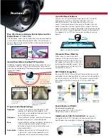
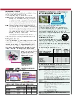


Easy-to-Manage Installation,
Setup and Adjustment
Enclosed within the housing are an integrated lens, a motor and a
pan/tilt mechanism. Attachment to the power supply base by simply
sliding the release levers simplifies installation at the point of surveil-
lance. The settings circuit board is detachable for access to protocol,
address and other switch settings, and the VAC-70 controller (sold
separately) and can be connected after installation to allow adjust-
ment of PTZ control and other settings from an on-screen menu.
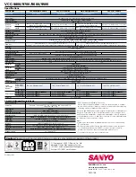
Model number codes
Camera type
8
36x, Day/night
7
36x, Color
6
30x, Day/night
5
30x, Color
Dome cover
C
Clear cover
S
Smoked cover
Power
0 0
AC24V
Housing type
I N
Surface cover
E M
In-ceiling
E X
Outdoor housing
Terminal side
(Side-A)
DIP switch side
(Side-B)
Alarm inputs (8)
Alarm outputs (2)
RS-485A/RS-485B
Address setting
Baud rate setting
RS-485/Coax setting
SSP/Pelco setting
Termination setting
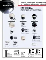
Camera Unit/Power Supply Base
Mounting Brackets
(Sold separately)
Housings
(Sold separately)
VA-80EX
Outdoor Housing
VA-CM8C
Clear dome cover for outdoor housing
VA-CM8S
Smoked dome cover for outdoor housing
VA-CZ80
Smoked dome cover for indoor housing
VA-80F
Surface Cover
Dimensions
Unit: mm (inch)
Model configurations example
Model name
VCC-9800EXC
VCC-9500EMC
VCC-9700INS
Camera unit
VCC-MC800
VCC-MC500
VCC-MC700
Power basement
VA-84S
VA-84S
VA-84S
Housing
VA-80EX
VA-80ME
VA-80F
Dome cover
VA-CM8C
VA-CZ80
+
+
+
VA-80ME
In-Ceiling Bracket
(closed type)
VA-80MF
In-Ceiling Bracket (open type)
ø192 (7.6)
ø109.7 (4.3)
ø190.2 (7.5)
ø28.5 (1.1)
ø216 (8.5)
101.1 (4.0)
111.5 (4.4)
ø216 (8.5)
51.3
(2.0)
152 (6.0)
162.5 (6.4)
Release
lever
ø248 (9.8)
ø146
(5.7)
ø224 (8.8)
Dome Cover
265.1 (10.4)
192 (7.6)
181.6 (7.1)
6 (0.2)
+
+
+
+
+
+
+
+
Slide the camera unit’s two release levers
and lock the power supply base into posi-
tion. No special tools required for camera
unit installation or removal.
Safety Cable
Equipped with a safety
cable that connects the
housing and power sup-
ply base to prevent the
camera unit from falling.
Detachable Settings
Circuit Board
4-ø4.5 (0.2)
P.D ø168 (6.6)
ø137.4 (5.4)
ø147.5 (5.8)
ø186 (7.3)
ø136 (5.4)
57.3
(2.3)
107.2 (4.2)
191.5 (7.5)
VA-80BP
Pendant Mounting
Bracket
VA-80BW
Wall Mounting Bracket
VA-80A
Attachment
VA-80AP
Pole Mounting Adaptor
VA-80AC
Corner Mounting Adaptor
45 (1.8)
ø194 (7.6)
300 (11.8)
329 (13.0)
ø96 (3.8)
ø130 (5.1)
ø96.5 (3.8)
239.8 (9.4)
191.5 (7.5)
191 (7.5)
4-ø8.5 (0.3)
P.D ø101.6 (4.0)
45
°
90˚
119 (4.7)
260.4 (10.3)
172.8 (6.8)
100 (3.9)
193 (7.6)
127 (5)
193 (7.6)
50 (2.0)
ø85–ø165 (3.3–6.5) (TBD)
Basic camera settings
can be made while hold-
ing the settings circuit
board in hand, as the
board is detachable from
the power supply base.
The I/O side of the board
features 8 input and 2
output terminals for
alarm signals.
Detachable without discon-
necting of power cable
ring camera performance, housings, mounting brackets and more—
nstallation work and maintenance is now easier than ever before.