
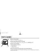
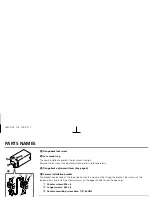


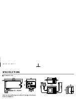

PARTS NAMES
1
Power indicator (POWER)
Comes on when the power to the camera is on.
2
Video output connector (VIDEO OUT: BNC type)
Connect this connector to a device such as a VCR or monitor with a
VIDEO IN
connector.
3
Control terminal (CONTROL)
Manual colour/black and white setting
•
G (ground) terminal
•
C (colour) terminal
•
B (black and white) terminal
4
External sync composite video signal input connector (VBS IN: BNC type)
Connect to this connector the synchronizing signal output from a synchronizing signal device or the composite
signal of a video distributor.
5
12 V DC input terminal (12 V DC, NC)
6
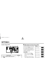
Camera setup section (under the cover)
These settings are for when using a 1/3 inch CS mount
DC
(without
EE
internal amplifier) type lens. However,
if due to installation conditions or environment the settings may need to be modified for best results (see
"
SETTINGS
").
To access the controls, loosen the cover fixing screw
A
, then remove the cover.
7
Lens iris output connector (LENS)
This 4-pin connector is used to send the DC control signal and power supply to an auto-iris type lens.
1
4
5
2
NC + –
G C B
3
6
7
A
L53U2/XE GB 1999, 9, 7
English
3


