background image

SANYO INDUSTRIAL VIDEO

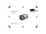
B/W VIDEO CAMERA LIMITED WARRANTY

OBLIGATIONS

In order to obtain warranty service, the product must be delivered to and picked up from an Authorized Sanyo Service Center at the user’s expense, unless specifically stated otherwise in this warranty. The names and
addresses of Authorized Sanyo Service Centers may be obtained by writing to SFS Corporation, SFC’s warranty administrator, at any of the addresses listed below, or by calling (toll-free) 1-800-421-5013.

New Jersey Office
210 Riser Road
Little Ferry, NJ 07643
201-641-3000

California Office
1200 W. Artesia Blvd.
Compton, CA 90220
310-537-5830

Illinois Office
900 N. Arlington Heights Rd.
Itasca, IL 60143
708-775-1414

THIS WARRANTY IS VALID ONLY ON SANYO PRODUCTS PURCHASED OR RENTED IN THE UNITED STATES OF AMERICA, EXCLUDING HAWAII AND ALL U.S. TERRITORIES AND PROTECTORATES. THIS
WARRANTY APPLIES ONLY TO THE ORIGINAL RETAIL USER. THE ORIGINAL DATED BILL OF SALE, SALES SLIP OR RENTAL AGREEMENT MUST BE SUBMITTED TO THE AUTHORIZED SANYO SERVICE CENTER
AT THE TIME WARRANTY SERVICE IS REQUESTED.
Subject to the OBLIGATIONS above and EXCLUSIONS below, SANYO FISHER (USA) CORPORATION warrants this SANYO product against defects in materials and workmanship for the periods specified below. SFC
will repair or replace (at its option) the product and any of its parts which fail to conform to this warranty. The warranty period commences on the date the product was first purchased or rented at retail.

LABOR

PARTS

IMAGE DEVICE

3 YEARS

3 YEARS

3 YEARS

EXCLUSIONS

This warranty does not cover (A) the adjustment of customer-operated controls as explained in the appropriate model’s instruction manual, or (B) the repair of any product whose serial number has been altered, defaced
or removed.
This warranty shall not apply to the cabinet or cosmetic parts, antenna, knobs, batteries or image burns to projection or picture tubes caused by electronic devices or games.
This warranty does not apply to uncrating, setup, installation, removal of the product for repair or reinstallation of the product after repair.
This warranty does not apply to repairs or replacements necessitated by any cause beyond the control of SFC including, but not limited to, any malfunction, defect or failure caused by or resulting from unauthorized
service or parts, improper maintenance, operation contrary to furnished instructions, shipping or transit accidents, modification or repair by the user, abuse, misuse, neglect, accident, incorrect power line voltage, fire,
flood or other Acts of God, or normal wear and tear.
The foregoing is in lieu of all other expressed warranties and SFC does not assume or authorize any party to assume for it any other obligation or liability.
THE DURATION OF ANY WARRANTIES WHICH MAY BE IMPLIED BY LAW (INCLUDING THE WARRANTIES OF MERCHANTABILITY AND FITNESS) IS LIMITED TO THE TERM OF THIS WARRANTY. IN NO EVENT
SHALL SFC BE LIABLE FOR SPECIAL, INCIDENTAL OR CONSEQUENTIAL DAMAGES ARISING FROM OWNERSHIP OR USE OF THIS PRODUCT, OR FOR ANY DELAY IN THE PERFORMANCE OF ITS OBLIGATIONS
UNDER THIS WARRANTY DUE TO CAUSES BEYOND ITS CONTROL.
SOME STATES DO NOT ALLOW LIMITATIONS ON HOW LONG AN IMPLIED WARRANTY LASTS AND/OR DO NOT ALLOW THE EXCLUSION OR LIMITATION OF CONSEQUENTIAL DAMAGES, SO THE ABOVE
LIMITATIONS AND EXCLUSIONS MAY NOT APPLY TO YOU.
THIS WARRANTY GIVES YOU SPECIFIC LEGAL RIGHTS. YOU MAY HAVE OTHER RIGHTS, WHICH VARY FROM STATE TO STATE.

ATTENTION

For your protection in the event of theft or loss of this product, please fill in the information below for you own personal records.

Model No._____________________________________________________________________

Serial No. _____________________________________________________________________
(Located on back or bottom side of unit.)

Date of Purchase _______________________________________________________________

Purchase Price _________________________________________________________________

Where Purchased _________________________________________________________________________________________________________________________________________________

L73T4/US GB 1999, 

8, 

3

14 

English

Summary of Contents for VCB-3424

Page 1: ...INSTRUCTION MANUAL VCB 3424 B W CCD Camera About this manual Before installing and using the camera please read this manual carefully Be sure to keep it handy for later reference L73T4 US GB 1999 8 3 ...

Page 2: ...to uncrating setup installation removal of the product for repair or reinstallation of the product after repair This warranty does not apply to repairs or replacements necessitated by any cause beyond the control of SFC including but not limited to any malfunction defect or failure caused by or resulting from unauthorized service or parts improper maintenance operation contrary to furnished instru...

Page 3: ...interline transfer method 1 3 CCD approx 270 000 picture elements Low smear anti blooming low lag no burning and no geometric distortion using the CCD solid state image device 100 solid state components giving excellent immunity to shock and vibration Not subject to interference from magnetic or electrostatic fields High sensitivity minimum required illumination of 0 07 lux with F1 2 lens Horizont...

Page 4: ...used in accordance with the instructions may cause harmful interference to radio communications However there is no guarantee that interference will not occur in a particular installation If this equipment does cause harmful interference to radio or television reception which can be determined by turning the equipment off and on the user is encouraged to try to correct the interference by one or m...

Page 5: ...r audio speakers the magnetic field they generate will distort the image Protect from humidity and dust To prevent damages to the camera do not install it where there is greasy smoke or steam where the dampness may get too high or where there is a lot of dust Protect from high temperatures Do not install close to stoves or other heat generating devices such as spotlights etc or where it could be s...

Page 6: ... 4 24 V AC input terminal 24 V AC GND Connect to 24 V AC UL listed class 2 power supply 5 Camera setup section under the cover These settings are for when using a 1 3 inch CS mount DC without EE internal amplifier type lens However if due to installation conditions or environment the settings may need to be modified for best results see SETTINGS To access the controls loosen the cover fixing screw...

Page 7: ...on bracket The bracket can be fixed at the top or bottom of the camera When fixing the bracket be sure to use the longer screws and install the shorter screws on the opposite side to seal the openings 1 Shorter screws M3 x 4 2 Longer screws M3 x 6 3 Camera mounting screw hole 1 4 20 UNC CAUTION When installing the camera support select a location that can support the total weight of the camera and...

Page 8: ...are available on the lens for iris adjustments Set the A I LENS switch to the VIDEO position Compatible auto iris lenses 1 3 inch Sanyo DC type lens VIDEO type lens VCL CS8LY Standard angle f 8 mm Standard angle f 9 mm VCL CS4LY Wide angle f 4 mm Telephoto angle f 12 mm VCL CS2LY Ultra wide angle f 2 8 mm More telephoto angle f 16 mm If using a VIDEO type auto iris lens Set the ALC and LEVEL contr...

Page 9: ...e lens To allow for flange back adjustment install the supplied C mount adaptor on the lens mount then carefully align the lens mount with the camera opening and turn the lens slowly to install it 3 Connect the lens plug to the lens iris output connector LENS on the side of the camera When using lenses from other makers the plug shape may not correspond to the terminal on the camera In such a case...

Page 10: ...ent If the pick up surface is not correctly positioned with relation to the lens focal point the picture will be out of focus in particular when using auto iris power zoom lenses sold separately If that is the case adjust the flange back position as described below 1 Using a screwdriver loosen the FLANGE BACK LOCK screw M2 Set the zoom lens to the maximum telephoto position set the focus using the...

Page 11: ... listed wire rated VW 1 should be used for the 24 V AC cable input terminal 3 Insert the plug of this power cord into a wall outlet The POWER indicator A will light Adjust the picture on the monitor using the Brightness and Contrast controls Coaxial cable type and maximum length Cable type RG 59U 3C 2V 250 m maximum Cable type RG 6U 5C 2V 500 m maximum Cable type RG 11U 7C 2V 600 m maximum CAUTION...

Page 12: ...en the EI switch is set to the ON position do not use an auto iris lens If used under fluorescent light the image may flicker In such a case change to incandescent lighting or set the EI switch to the OFF position and use an auto iris lens When shooting bright subjects pay attention to the light angle in order to avoid or minimize the smear phenomenon effect When using an auto iris lens for indoor...

Page 13: ...sition the image displayed on the monitor will be reversed horizontally For example this setting can be used if the camera is installed at the back of a truck or bus and looking towards the back the image will be as seen in the mirrors Backlight compensation setting Use an auto iris lens and set the BLC switch to the ON position to engage the backlight compensation function If using a VIDEO type a...

Page 14: ...If it still does not perform correctly please consult your dealer or a Sanyo Authorized Service Centre No picture on the monitor screen Is the power turned on to all connected devices Is the voltage correct Are all the signal connecting cables correctly connected Is the lighting sufficient Has the lens cap been removed Is the lens type DC or VIDEO correctly selected Depending on the type of lens t...

Page 15: ...tronic iris range 0 07 lux to 42 000 F 1 2 lens 0 1 lux to 57 000 F 1 4 lens Flange back 12 5 mm 0 8 mm Gamma correction γ 0 45 Lens mount CS mount or C mount with the supplied adaptor Environmental conditions Temperature 10 C 50 C Humidity less than 90 no condensation Power supply 24 V AC 60 Hz Power consumption 2 3 W with auto iris lens 1 4 W without auto iris lens Weight Approx 330 g without le...

Page 16: ...board monitors software tv dvd and othes Manual users user manuals user guide manual owners manual instruction manual manual owner manual owner s manual guide manual operation operating manual user s manual operating instructions manual operators manual operator manual product documentation manual user maintenance brochure user reference pdf manual ...

Reviews: