– 14 –
a
b
c
B
A
A
B
C
1
2
3
4
5
6
7
8
9
9
10
10
11
12
13
14
15
16
17
18
19
20
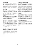
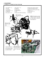
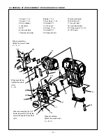
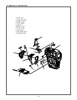
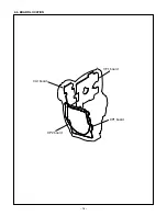
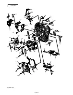
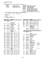
2-3. REMOVAL OF LENS ASSEMBLY, CP1 BOARD AND CA1 BOARD
1. Screw 1.7 x 3
2. Screw 1.7 x 4
3. Earth speaker
4. Connector
5. FPC
6. Lens assembly
7. Remove the solder.
When assembling,
tighten the screws order.
A
→
B
→
C
When assembling,
tighten the screws
order.
A
→
B
When assembling,
tighten the screws order.
a
→
b
→
c
8. Screw 1.7 x 4
9. Two screws 1.7 x 4
10. Holder CP2
11. CP1 board
12. Screw 1.7 x 4
13. Holder CP1
14. Spring lock batt
When reassembling the CP1
board, be careful not to let the
chip touch against the cabinet
right.
15. Spring batt eject
16. Terminal batt
17. Dec cabi right
18. Lever lock battery
19. Three screws 1.4 x 3.5
20. CA1 board


