background image

Summary of Contents for TRC-7060

Page 1: ... 142 605 03 NZ 142 605 04 UK Erase system DC erase Output power 1000 mW MAX Fast forward 420 sec MC 40N Loud speaker 77 mm D 8 ohms Rewind time 150 sec MC 40N Dimensions 240 W x 186 D x 53 H mm Wow and flutter 1 0 o RMS Weight 1 2kg Frequency response 250 Hz 6 000 Hz DC input DC9V Specifications subject to change without notice REFERENCE No SM580482 ...

Page 2: ...not loosen the two screws fastening the Rewind Solenoid and adjust the clearance by slowly moving the Solenoid while inserting the Plunger into the Solenoid as illustrated After the adjustment tighten the fastening screws and secure them with paint or glue d PLAY SOLENOID ADJUSTMENT 1 2 3 4 5 Fully insert the Plunger into the Play Solenoid and check to see that the clearance between the Play Plate...

Page 3: ... with the unit in an upright position as illustrated If necessary adjust the clearances as follows To obtain the clearance of O between the Flywheel and the Flywheel Support slowly turn the Flywheel Thrust counterclockwise Then fully push the oil cut washer down as illustrated Turn the Flywheel Thrust clockwise until the clearance between the Flywheel and Flywheel Support becomes 0 5 f 0 1 mm when...

Page 4: ...etize the heads by using a I PLAY AD head eraser Be sure to clean the heads before attempting to make any adjustment b Head Azimuth Adjustment 1 Load the test tape A BEX SSC I 584 etc for azimuth adjustment 2 Press the PLAY button 3 Use a cross tip screwdriver to turn the screw for azimuth adjustment so that the outputs maximized 4 After completion of the adjustment use thread lock TB 1 401 B to s...

Page 5: ...L EXPLODED VIEW CABINET CHASSIS 4 ...

Page 6: ...SPRING LID CASSETTE ASSY CABINET BOTTOM KNOB PLATE KNOB BUTTON ERASE BUTTON PLAY BUTTON FF BUTTON REW BUTTON STOP BUTTON DUMMY BUTTON SELECT BUTTON POWER BRACKET BUTTON PLAY BRACKET BUTTON DUMMY BRACKET BUTTON POWER BRACKET FIX SPEAKER LUG CUSHION CUSHION PLATE JACK SHEET SHEET Description SCR TPG PAN 3X16 BOTTOM SCR PAN 3X8 SCR PAN 2 6X6 AMP PWB SCR PAN SW 2 6X6 AMP PWB SCR TPG PAN 3X8 SPEAKER SC...

Page 7: ...6 1254 620 006 1254 620 006 1261 620 006 1278 Description IC UPC358C IC BA6104 IC LA5522 POTENTIOMETER 201 Pc NJL5141E A GR PHOTO COUPLE GP2S22 A TR 2SC536 E NP TR 2SC536 F NP TR 2SC536 E NP TR 2SC536 F NP TR 2SC536 E NP TR 2SC536 F NP TR 2SD545 E NP TR 2SD545 F NP TR 2SC536 E NP TR 2SC536 F NP TR 2SA608 F NP TR 2SC536 E NP TR 2SC536 F NP TR 2SD545 E NP TR 2SD545 F NP TR 2SA608 F NP TR 2SC536 E NP...

Page 8: ...EXPLODED VIEW TAPE MECHANISM 1l _ 3 W 2 fl 24 23 1 4 46 24 47 Q 2 7 48 77 i l A r J iol 1ul 81 4 1 9 102 6 101 1 100 0 98 1 Q loo 2 go 00 7 ...

Page 9: ... SPRING BRAKE BRACKET BRAKE ASSY BASE FLYWHEEL ASSY SCR PAN 2X7 PIVOT FLYWHEEL BALL WASHER RING E 2 5 HOLDER BEARING BRACKET CASSETTE ASSY SCR TPG PAN 2X4 SPRING EJECT EYELET HOLDER CASSETTE ASSY CUSHION GEAR DAMPER RING E 2 5 BRACKET CASSETTE ASSY SCR TPG PAN 2X4 R P HEAD SCR PAN 2X4 SCR CYL 2X4 SPACER HEAD SPRING AZIMUTH ERASE HEAD BASE HEAD ASSY SCR PAN 2 6X4 LUG ARM BRAKE LEVER IDLER ASSY SPAC...

Page 10: ...C AMP RecordEIJ RecordEO VCC RIPSwilctr v Oulpul B Input B Inpul B 8 1 6 5 B A 2 3 4 OulmrlA Irwerlinq Non4nverlln9 GNO Input A Input A l I T T T T T 1 I L Vooi joRegulator I II J 4 i J I I l I I I I I i I I OUTPUTI OUTPUT2 OUTPUT 3 OUTPUT 4 GNU OUTPUI 5 Vmff INPUT Vcc W IC501 LA5522 Motor Control A nnam7nn1 ACCESSORIES PAH i S PUU I LUN I 15ULJ d I 3 02 400 060 9 ...

Page 11: ...cked up by the MPU IC3 as the Cue Tone SignaL Pin9 PEO of IC3 goes to high approx 1 2V for approximately 2 seconds releasing the Play Solenoid SLI At the same time pinl 5 PFO of IC3 goes to high approx 2V and the Motor M 1 drops from high speed to normal rotation d e f During rewind the input Cue Tone Signal goes to approxi mately 650 2200 Hz This signal is boosted at IC4 and when over Q16 turns o...

Page 12: ... 3014 Search LWrchl J Mmow Control Circuit IC5 Q12 Is t PI Cir 03 H02 Erne Held r 9V x I T Rewind Drive Circuit Q7 Q8 MPIJ IC3 I S4 Ccsaetle stitch 3 t YO 4 60 50 w Volhge Regulator Oslo 2 JI Rtmole Control Jack T o I HOI 2 PlayHead Search c I lhck tct RotationDetection Circuit Control Pcl 917 VR501 SpeedControl CueToneDetectioncircuit 4 Search Erise ...

Page 13: ...SCHEMATIC DIAGRAM 4JTE 133 Gin B 2 50 6 0 A m 12 do L17 50 l w a Pc 1 NJL 5141EB E 017 A60t l m g z L Q13 This is a basic schematic diagram 12 ...

Page 14: ...rl FG 7 3911 7 Q w I Iii Ill Vvq R 10K y q 7 6 11 1 m I II LM641 E3 1850 li L Q ...

Page 15: ...WIRING DIAGRAM r El J4 ExT POWER JACK I 11 I D 11 L 1 r I I J I I I I m I 1 L 14 ...

Page 16: ...6 Ji GRAY BROWN N2 SP1 SPEAKER GREEN VIOLET HO J CASSETTE SWITCH 9E D SL1 PLAY SOLENOID I CN3 CONNECTOR P W B RED I f GRAY 1 HD1 1 I e REC PLAY HEAO AlR310 It YELLOW HD1 2 REC PLAV HEAD SEARCH al J3 EARPHONE JACK TAPE MECHANISM 15 ...

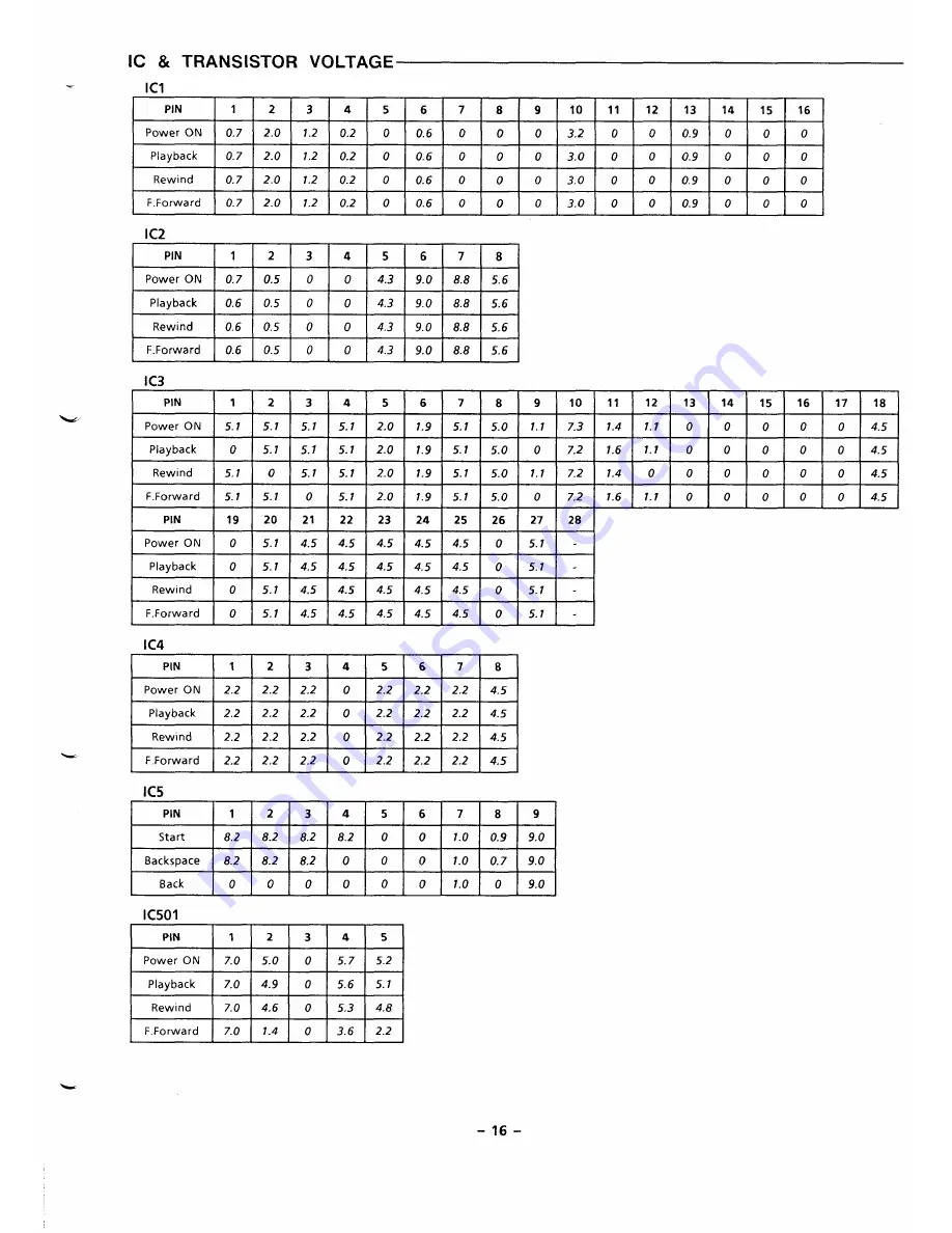
Page 17: ...1 9 5 1 5 0 0 7 2 1 6 1 1 0 0 0 0 0 4 5 Rewind 5 1 0 5 1 5 1 2 0 1 9 5 1 5 0 1 1 7 2 1 4 0 0 0 0 0 0 4 5 F Forward 5 1 5 1 0 5 1 2 0 1 9 5 1 5 0 0 7 2 1 6 1 1 0 0 0 0 0 4 5 PIN 19 20 21 22 23 24 25 26 27 28 Power ON o 5 1 4 5 4 5 4 5 4 5 4 5 0 5 1 Playback o 5 1 4 5 4 5 4 5 4 5 4 5 0 5 1 Rewind o 5 1 4 5 4 5 4 5 4 5 4 5 0 5 1 F Forward o 5 1 4 5 4 5 4 5 4 5 4 5 0 5 1 IC4 PIN 1 2 3 4 5 6 7 8 Power ...

Page 18: ...8 1 5 1 0 3 0 9 0 6 0 5 0 0 0 6 8 1 5 1 H w Q15 I Q16 I Q17 I QIB I B c E B c E B c E B c E 0 6 0 0 0 5 1 I o 5 1 0 7 0 0 Playback o 0 7 0 0 6 0 0 Rewind o 0 7 0 0 6 0 0 0 6 0 0 0 5 1 0 5 1 0 0 6 0 0 6 0 0 0 5 1 0 5 1 0 7 0 0 lF Forward lOIO 71010 61010 0 610101015 1101 I 15 11010 6101 Q503 Q504 Q505 Q506 BICIEIBICIEIB ICIE BICIEI 79 6 7 5 0 5 0 4 6 5 2 5 2 6 9 4 6 6 9 4 6 5 1 5 1 6 9 5 1 5 1 6 3 ...

Reviews: