-27-
Electrical Adjustments
1. Receive the 100%whole-white computer signal with
Computer 1 [Analog RGB]
mode.
2. Enter the service mode.
3. Measure luminance on the screen with the luminance
meter. It is
A
for the reading of luminance meter.
4. Change the signal source to the 50%whole-white
computer signal with
Computer 1 [Analog RGB]
mode.
5. Select group no. “
4
”, Item no. “
6
” and change the Data
value to make the reading of luminance meter to be
A
x 23%
.
Luminance adjustment adjustment [PC]
7
1. Receive the 16-step gray scale composite video sig-
nal with
Video
mode.
2. Enter the service mode.
3. Connect a digital voltmeter to test point “
TPVRB
” (+)
and chassis ground (-).
4. Select group no. “
5
”, Item no. “
17
” and adjust the volt-
age to be
1.0
±0.05Vdc by changing the Data value.
5. Connect a digital voltmeter to test point “
TPGVRT
(+)
and chassis ground (-).
6. Select Item no. “
18
” and adjust the voltage to be
2.5
±0.05Vdc by changing the Data value.
A/D Ref. Voltage adjustment [Video]
8
1. Receive the 16-step gray scale composite video sig-
nal with
Video
mode.
2. Enter the service mode.
3. Connect an oscilloscope to test point “
TP13G
” (+)
and chassis ground (-).
4. Select group no. “
3
”, Item no. “
1
” and adjust the ampli-
tude “a” to be
1.35
±0.1V by changing the Data value.
* This changes all the RGB amplitude at the same
time. Item no. “2” can be adjusted for G only.
5. Connect an oscilloscope to test point “
TP13B
” (+)
and chassis ground (-).
6. Select Item no. “
3
” and adjust the amplitude “a” to be
1.35
±0.1V by changing the Data value.
7. Connect an oscilloscope to test point “
TP13R
” (+)
and chassis ground (-).
8. Select Item no. “
4
” and adjust the amplitude “a” to be
1.35
±0.1V by changing the Data value.
(a)
A/D Input adjustment [Video]
9
1. Receive the 100%whole-Black composite video sig-
nal with
Video
mode.
2. Enter the service mode.
3. Connect an oscilloscope to test point “
TP531
” (+) and
chassis ground (-).
4. Select group no. “
5
”, Item no. “
11
” and adjust the
black level to be maximum amplitude by changing the
Data value.
5. Connect an oscilloscope to test point “
TP501
” (+) and
chassis ground (-).
6. Select Item no. “
12
” and adjust the black level to be
maximum amplitude by changing the Data value.
7. Connect an oscilloscope to test point “
TP561
” (+) and
chassis ground (-).
8. Select Item no. “
13
” and adjust the black level to be
maximum amplitude by changing the Data value.
Note: This adjustment should be done after A/D Input
adjustment [Video].
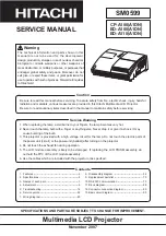
Pedestal Lebel
Black Lebel
Pedestal adjustment [Video]
10
1. Receive the 16-step gray scale video composite sig-
nal with
Video
mode.
2. Enter the service mode.
3. Connect an oscilloscope to test point “
TP531
” (+)
and chassis ground (-).
4. Select group no. “
4
”, Item no. “
3
” and adjust the white
level to be minimum amplitude by changing the Data
value.
5. Connect an oscilloscope to test point “
TP501
” (+)
and chassis ground (-).
6. Select Item no. “
4
” and adjust the white level to be
minimum amplitude by changing the Data value.
7. Connect an oscilloscope to test point “
TP561
” (+)
and chassis ground (-).
8. Select Item no. “
5
” and adjust the white level to be
minimum amplitude by changing the Data value.
(a)
White Level
Video Gain adjustment [Video]
11
Summary of Contents for PLC-XT10
Page 57: ... 57 IC Block Diagrams AD8185ARU Selector IC3001 AD9888KS140 A D IC201 ...
Page 58: ... 58 BA6920F Motor Drive IC5561 IC Block Diagrams BA6287F Motor Drive IC5501 IC5531 IC6501 ...
Page 59: ... 59 IC Block Diagrams BA7078AF SynC Detector IC7201 BA7655 Audio Pre amp IC001 ...
Page 60: ... 60 CXA2101AQ RGB Matrix IC4101 IC Block Diagrams DB7600 Sync Switch IC3021 IC3022 ...
Page 61: ... 61 IC Block Diagrams ICS1523M PLL IC4231 L306070D D A Sample Hold IC501 IC530 IC561 ...
Page 62: ... 62 M62392 D A IC3291 M62393 D A IC281 IC4881 IC Block Diagrams ...
Page 63: ... 63 M62399 D A IC1501 IC1531 ML60851 USB Driver IC9801 IC Block Diagrams ...
Page 65: ... 65 TC90A69F PAL 3L Y C Separation IC2101 IC Block Diagrams TB1274AF Video Decoder IC1101 ...
Page 66: ... 66 TDA1517ATW Audio Output IC031 IC Block Diagrams ...
Page 96: ...MD3 XT1000 Electrical Parts List 96 Key No Part No Description Key No Part No Description ...
Page 99: ...MD3 XT1000 99 Mechanical Parts List L4 S3 S3 L10 S5 S5 ...
Page 100: ...MD3 XT1000 100 Mechanical Parts List L11 S3 S3 L1 L1 a L1 b L12 L1 c Mounting Base Focus Zoom ...
Page 103: ...MD3 XT1000 103 Mechanical Parts List ...
Page 104: ... MD3A Dec 2002 BB 400 Printed in Japan SANYO Electric Co Ltd ...