-38-
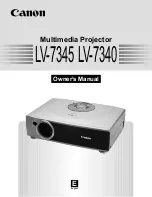
Optical Adjustment
Yellow/magenta color offset
1-2. Mirror (B) adjustment
1
Loosen 1 screw
e
and 1 screws
G
.
2
Move the Mirror-B to disappear the color band (Yellow/Magenta) on
the top/bottom and left/roght of the screen.
1) Insert a slot driver into the slot
F
and turn it to move the image
vertically as shown in
Fig.1-4
.
2) Insert a slot driver into the slot
H
and turn it to move the image
horizontally as shown in
Fig.1-3
.
3
Tighten screws
e
and
G
to fix the Mirror-B unit.
e
F
G
H
Cyan/Magenta
Magenta/Cyan
(target screen image)
Fig.1-3
Fig.1-4
Yellow/magenta color offset
Summary of Contents for PLC-WM4500
Page 90: ... 90 IC Block Diagrams CXA7009 S H IC501 IC531 IC561 CXD3540 Digital Gamma Correction IC401 ...
Page 91: ... 91 IC Block Diagrams FA5502 P F Control IC601 ISL98001 A D Converter IC2201 ...
Page 92: ... 92 IC Block Diagrams M62393 DAC IC7801 LV49152 Audio Output IC001 ...
Page 93: ... 93 IC Block Diagrams PIC18F67 Network IC8801 NJW1156 Audio Selector IC5001 ...
Page 94: ... 94 IC Block Diagrams PW392 Scaler IC301 STR A6079 Power switching IC603 ...
Page 95: ... 95 IC Block Diagrams TE7783 I O Expander IC4801 STR Z2156 Power switching IC651 ...
Page 96: ... 96 IC Block Diagrams THS7347 3 CH Analog SW IC5231 IC5271 IC5251 ...
Page 103: ... 103 Parts Location Diagrams KP8 WM450000 KP8 WM4500L00 Mirror B assembly S07 S07 S07 L11 M08 ...
Page 142: ... KP8AL July 2010 DC 50 Printed in Japan SANYO Electric Co Ltd ...