background image

56

Controles básicos

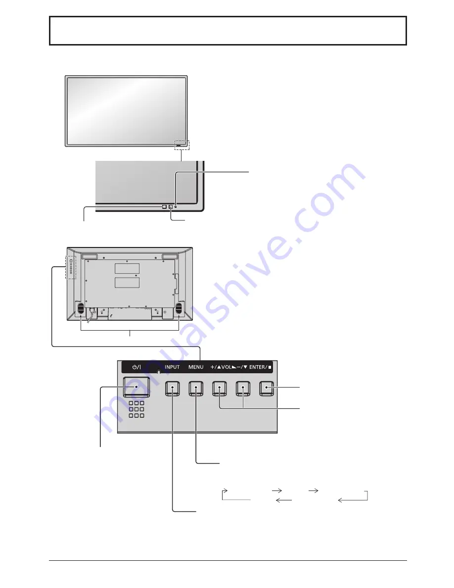
Encendido/Apagado de la pantalla MENÚ

Cada vez que se pulsa el botón MENU, la pantalla de 

menú se conmuta. (vea la página 58)

Visión normal

Imagen

Configuración

Sonido

Pos. /Tamaño

Ajuste de volumen

Subida  “+”  y  bajada  “–”  del  volumen  

Cuando se visualice la pantalla del menú:

“+”: presione para mover el cursor hacia arriba

“–”: presione para mover el cursor hacia abajo

(vea la página 58)

Sensor de control 

remoto

Interruptor principal

Altavoces

Sensor de brillo

Capta el brillo en el entorno de la 

pantalla.

Unidad principal

Piloto de encendido

Se enciende el piloto de funcionamiento.

• Desconectado ... El indicador está apagado (La unidad 

consume algo de energía siempre 

que  el  cable  de  alimentación  se 

mantiene conectado a la toma de 

corriente.)

• Espera  .......... Rojo

• Conectado ..... Verde

• Energía monitor (DPMS)

   ....................... Naranja (Señal PC IN o DVI-D IN.)

Botón de introducción/aspecto 

(vea la página 58)

Tecla INPUT (Selección de la señal de entrada)

(vea la página 55)

Summary of Contents for PID-42NE1

Page 1: ...INIEN VOR DEM AUSPACKEN UND DER INSTALLATION BELANGRIJK LEES DEZE HANDLEIDING VOOR HET UITPAKKEN EN INSTALLEREN IMPORTANTE LEGGERE ATTENTAMENTE LE SEGUENTI ISTRUZIONI PRIMA DI DISIMBALLARE E INSTALLARE IL PRODOTTO INSTALLATION GUIDELINES CONSIGNES D INSTALLATION INSTRUCCIONES DE INSTALACIÓN INSTALLATIONSRICHTLINIEN INSTALLATIEHANDLEIDING ISTRUZIONI DI INSTALLAZIONE PID 42NE1 PID 47NE1 PID 42NE1U P...

Page 2: ... near any heat sources such as radiators heat registers stoves or other apparatus including amplifiers that produce heat 9 Do not defeat the safety purpose of the polarized or grounding type plug A polarized plug has two blades with one wider than the other A grounding type plug has two blades and a third grounding prong The wide blade or the third prong are provided for your safety If the provide...

Page 3: ...the display Only using furniture that can safely support the display Ensuring the display is not overhanging the edge of the supporting furniture Not placing the display on tall furniture for example cupboards or bookcases without anchoring both the furniture and the display to a suitable support Not standing the displays on cloth or other materials placed between the display and supporting furnit...

Page 4: ... radio TV technician for help Use of shielded cable is required to comply with class B limits in Subpart B of Part 15 of FCC Rules Do not make any changes or modifications to the equipment unless otherwise specified in the instructions If such changes or modifications should be made you could be required to stop operation of the equipment Model Number PID 42NE1U PID 47NE1U Trade Name Sanyo Respons...

Page 5: ... that conforms to VESA standards VESA 400 400 must be used When installing the Display vertically be sure to install the power switch onto the bottom of the Display When using the LCD Display The Display is designed to operate on 220 240 V AC 50 60 Hz PID 42NE1 PID47NE1 The Display is designed to operate on 110 127 V AC 50 60 Hz PID 42NE1U PID47NE1U Do not cover the ventilation holes Doing so may ...

Page 6: ... soft dry cloth If the cabinet is particularly dirty soak the cloth in water to which a small amount of neutral detergent has been added and then wring the cloth dry Use this cloth to wipe the cabinet and then wipe it dry with a dry cloth Do not allow any detergent to come into direct contact with the surface of the Display If water droplets get inside the unit operating problems may result Avoid ...

Page 7: ...h Alkaline 4 Do not attempt to charge short circuit disassemble heat or burn used batteries 5 Battery replacement is necessary when remote control acts sporadically or stops operating the Display set 6 Do not burn or breakup batteries Batteries must not be exposed to excessive heat such as sunshine fire or the like PID 42NE1 PID 47NE1 PID 42NE1U PID 47NE1U 7 Remote Control Batteries Requires two R...

Page 8: ...ng Fix the cable in place using the bead band attached to the display 1 2 3 Remove the bead band Bundle the cables Attach the bead band Bead band Remove Bundle the cables Stopper Pass through to the back AV IN HDMI1 HDMI2 HDMI Input Terminal see page 10 COMPONENT RGB IN Component RGB Video Input Terminal see page 9 DVI D IN DVI D Input Terminal see page 10 SERIAL Control the Display by connecting ...

Page 9: ...RGB when RGB signal connection Accepts only RGB signals with Sync on G RCA BNC Adapter plug RCA BNC Adapter plug DVD Player DVD Player VCR Computer RGB Camcorder VIDEO and COMPONENT RGB IN connection Note Additional equipment cables and adapter plugs shown are not supplied with this set S Video Input Terminal Luminance Signal Color Signal Earth Color Signal Earth Luminance Signal 9 Connections ...

Page 10: ...2 13 2 T M D S data 2 14 5 V DC 3 T M D S data 2 shield 15 Ground 4 16 Hot plug detect 5 17 T M D S data 0 6 DDC clock 18 T M D S data 0 7 DDC data 19 T M D S data 0 shield 8 20 9 T M D S data 1 21 10 T M D S data 1 22 T M D S clock shield 11 T M D S data 1 shield 23 T M D S clock 12 24 T M D S clock Notes Additional equipment and cables shown are not supplied with this set Use the DVI D cable wit...

Page 11: ...and cables shown are not supplied with this set Sanyo recommends using a PC cable that includes a Ferrite core Do not set the horizontal and vertical scanning frequencies for PC signals which are above or below the specified frequency range Component Input is possible with the pin 1 2 3 of the Mini D sub 15P Connector To use sync input VBS signals use the connector which incorporates a 75 ohm term...

Page 12: ...ntered between the command and the parameter Ex CF_POWER_ON CR _ space Notes If a correct command is sent this unit will send a 000 command to the computer If an incorrect command is sent by mistake this unit will send a different command apart from 000 to the computer While the power is in stand by mode power turned off with remote control all operations except CF POWER ON will not respond Commun...

Page 13: ...ting the plug to the Wall Outlet Notes Main plug types vary between countries The power plug shown at right may therefore not be the type fitted to your set When disconnecting the AC cord be absolutely sure to disconnect the AC cord plug at the socket outlet first Press the Power switch on the Display to turn the set on Power On Power Indicator Green Connecting the AC cord plug to the Display Anno...

Page 14: ...xample Power On Off When first switching on the unit Following screen will be displayed when the unit is turned on for the first time Select the items with the remote control Unit buttons are invalid OSD Language PRESENT TIME Setup 1 Select the language 2 Set 1 Select DAY or PRESENT TIME 2 Setup DAY or PRESENT TIME Notes Once the items are set the screens won t be displayed when switching on the u...

Page 15: ...quipment which has been connected to the Display Input signals will change as follows PC PC input terminal in PC IN DVI DVI input terminal in DVI D IN HDMI1 HDMI input terminal in AV IN HDMI1 HDMI2 HDMI input terminal in AV IN HDMI2 VIDEO Video input terminal in AV IN VIDEO S VIDEO Component Component or RGB input terminal in COMPONENT RGB IN Component may be displayed as RGB depending on the sett...

Page 16: ...ff Switch Speakers Brightness Sensor Detects the brightness in the viewing environment Main Unit Power Indicator The Power Indicator will light Power OFF Indicator not illuminated The unit will still consume some power as long as the power cord is still inserted into the wall outlet Standby Red Power ON Green Power management DPMS Orange PC IN or DVI D IN signal Enter Aspect button see page 18 INP...

Page 17: ...changes to 30 minutes 60 minutes 90 minutes and 0 minutes off timer cancelled each time the button is pressed 30 60 0 90 When three minutes remain Off timer 3 will flash The off timer is cancelled if a power interruption occurs RECALL button Press the RECALL button to display the current system status 1 Input label 2 Aspect mode 3 Off timer The off timer indicator is displayed only when the off ti...

Page 18: ...ormal Viewing Picture Sound Pos Size Setup 2 Select the item 100 70 50 50 50 Picture Normal Normalise Normal Brightness Picture Mode Colour Contrast Backlight Tint Advanced settings MEMORY SAVE White balance Normal MEMORY LOAD MEMORY EDIT Sharpness 50 Example Picture menu Select Press Select 3 Set Adjust Press Adjust 4 Exit the menu Press Press to return to the previous menu Press several times ...

Page 19: ...hat cannot be adjusted is grayout Adjustable menu changes depending on signal input and menu setting On Screen Menu Displays 100 70 50 50 50 Picture Normal Normalise Normal Brightness Picture Mode Colour Contrast Backlight Tint Advanced settings MEMORY SAVE White balance Normal MEMORY LOAD MEMORY EDIT Sharpness 50 1 MULTI DISPLAY Setup Horizontal Scale Off A1 Location Vertical Scale Bezel V Adjust...

Page 20: ... 50p 24p 25p 30p 24sF 1250 1080 50i PC signals VGA SVGA XGA SXGA UXGA compressed Horizontal scanning frequency 30 110 kHz Vertical scanning frequency 48 120 Hz Connection terminals AV IN VIDEO S VIDEO AUDIO L R BNC Mini DIN 4PIN RCA Pin jack 2 1 0 Vp p 75 Ω Y 1 0 Vp p 75 Ω C 0 286 Vp p 75 Ω 0 5 Vrms HDMI 1 2 TYPE A Connector 2 COMPONENT RGB IN G Y B PB CB R PR CR AUDIO L R BNC BNC BNC RCA Pin jack...

Page 21: ...plicable for incorrect disposal of this waste in accordance with national legislation For business users in the European Union If you wish to discard electrical and electronic equipment please contact your dealer or supplier for further information Information on Disposal in other Countries outside the European Union These symbols are only valid in the European Union If you wish to discard these i...

Page 22: ...llez pas l appareil près d une source de chaleur telle qu un radiateur une chaudière une cuisinière ou un autre appareil y compris des amplificateurs produisant de la chaleur 9 N invalidez pas les caractéristiques de sécurité de la fiche polarisée ou avec mise à la terre Une fiche polarisée possède deux broches une plus large que l autre Une fiche avec mise à la terre possède deux broches et une t...

Page 23: ...imentation avec mise à la masse à trois broches Cette fiche ne peut être adaptée qu à une prise de courant avec mise à la masse Ceci est un dispositif de sécurité Si vous ne pouvez pas insérer la fiche dans la prise adressez vous à un électricien Ne modifiez pas la fiche avec mise à la masse 4 Pour éviter toute secousse électrique assurez vous que la broche de mise à la terre de la fiche du cordon...

Page 24: ...tilisation d un câble gainé est nécessaire pour que l installation soit conforme aux limites de la classe B de la section B de l article 15 du Règlement du FCC N apportez pas de changements ou modifications à l équipement à moins qu ils ne soient spécifiés dans les instructions Si vous effectuez de tels changements ou modifications vous pouvez être contraint d arrêter d utiliser l équipement Numér...

Page 25: ...rage de monture murale conforme à la norme VESA VESA 400 400 Si vous installez l écran verticalement assurez vous d installer le commutateur d alimentation en bas de l écran Utilisation de l écran LCD L écran a été conçu pour fonctionner sur secteur de 220 240 V 50 60 Hz PID 42NE1 PID 47NE1 L écran a été conçu pour fonctionner sur secteur de 110 127 V 50 60 Hz PID 42NE1U PID 47NE1U Ne couvrez pas ...

Page 26: ...ret est sale essuyez le avec un chiffon doux et sec Si le coffret est très sale plongez le chiffon dans de l eau additionnée d un peu de détergent neutre puis essorez le chiffon bien à fond Utilisez ce chiffon pour essuyer le coffret puis essuyez le avec un chiffon sec Veillez à ce que du détergent n entre pas en contact direct avec la surface de l écran Si des gouttes d eau pénètrent dans l appar...

Page 27: ...nts de pile exemple une pile au zinc carbone et une pile alcaline 4 Ne tentez pas de recharger les piles usagées ne les court circuitez pas ne les démontez pas ne les chauffez pas ne les jetez pas dans un feu 5 Le remplacement des piles s avère nécessaire lorsque la télécommande n agit plus que de façon irrégulière ou plus du tout 6 Ne brûlez pas ou ne brisez pas les piles Ne pas exposer les piles...

Page 28: ...HDMI Input Terminal reportez vous à la page 30 COMPONENT RGB IN Borne d entrée composantes vidéo RVB reportez vous à la page 29 DVI D IN Borne d entrée DVI D reportez vous à la page 30 SERIAL Contrôlez l écran en raccordant un PC reportez vous à la page 32 PCIN Borne d entrée PC reportez vous à la page 31 AV IN VIDEO Borne d entrée composite vidéo S VIDEO Borne d entrée S VIDEO reportez vous à la ...

Page 29: ...de Sélection entrée en composantes RVB dans le menu Configuration pour Composants lors de la connexion d un signal composantes ou pour RVB lors de la connexion d un signal RVB N accepte que les signaux RVB avec Synchro Sur V Fiche d adaptation RCA BNC Fiche d adaptation RCA BNC Lecteur DVD Lecteur DVD Magnétoscope Ordinateur Caméra RVB Borne d entrée S Vidéo Signal de luminance Signal de couleur T...

Page 30: ...déo DVI D N de broche Nom du signal N de broche Nom du signal 1 Données 2 T M D S 13 2 Données 2 T M D S 14 5 V CC 3 Blindage pour données 2 T M D S 15 Masse 4 16 Hot plug detect 5 17 Données 0 T M D S 6 Horloge DDC 18 Données 0 T M D S 7 Données DDC 19 Blindage pour données 0 T M D S 8 20 9 Données 1 T M D S 21 10 Données 1 T M D S 22 Blindage pour horloge T M D S 11 Blindage pour données 1 T M D...

Page 31: ...és sur cette illustration ne sont pas fournis avec cet appareil Sanyo conseille d utiliser un câble PC qui comprend un tore magnétique Ne réglez pas les fréquences de balayage horizontal et vertical pour les signaux PC à des niveaux supérieurs ou inférieurs aux limites de la plage de fréquence spécifiée L entrée en composantes est possible avec les broches 1 2 et 3 du connecteur Mini D sub 15 broc...

Page 32: ...tre la commande et le paramètre Ex CF_POWER_ON CR _ espace Remarques Si une commande correcte est envoyée cet appareil enverra une commande 000 à l ordinateur Si une commande incorrecte est envoyée par erreur cet appareil enverra une commande différente de 000 à l ordinateur Alors que le pouvoir est en stand by veille alimentation coupée avec la télécommande toutes les opérations sauf FC POWER ON ...

Page 33: ...hes secteur varient d un pays à l autre La fiche illustrée à droite n est peut être pas celle dont est équipé votre appareil Lorsque vous débranchez le cordon d alimentation faites le toujours d abord par sa fiche branchée dans la prise de courant Appuyez sur l interrupteur d alimentation de l écran pour le mettre sous tension Appareil allumé Témoin d alimentation Témoin vert Capteur de télécomman...

Page 34: ...télécommande Les touches de l appareil sont inopérantes Affichages à l écran Réglage de l heure actuelle 1 Sélectionnez la langue 2 Réglez 1 Sélectionnez Jour de la semaine ou Heure actuelle 2 Configurez Jour de la semaine ou Heure actuelle À partir de la deuxième mise en service l écran ci dessous s affiche pendant un moment l état de réglage est un exemple Remarques Une fois les options réglées ...

Page 35: ...qui aété raccordé à l écran Le signal d entrée change comme suit pour chaque pression PC HDMI1 HDMI2 Component VIDEO DVI PC Borne d entrée PC dans PC IN DVI Borne d entrée DVI dans DVI D IN HDMI1 Borne d entrée HDMI dans AV IN HDMI1 HDMI2 Borne d entrée HDMI dans AV IN HDMI2 VIDEO Borne d entrée vidéo dans AV IN VIDEO S VIDEO Component Borne d entrée composante ou RGB dans COMPONENT RGB IN Compone...

Page 36: ...nosité dans la pièce Appareil principal Témoin d alimentation Le témoin d alimentation s allume alors Appareil éteint Le témoin est éteint L appareil continue de consommer de l énergie aussi longtemps que le cordon d alimentation est branché sur la prise murale Appareil en veille Rouge Appareil allumé Vert Gestion alimentation DPMS Orange Signal PC IN et DVI D IN Touche de validation et format d i...

Page 37: ...ppareil est mis hors service ou que le niveau d écoute est modifié Zoom numérique Télécommande Touche R reportez vous à la page 38 Appuyez sur la touche R pour revenir à la page de menu précédente Réglage du volume Appuyez sur la touche de volume haut ou bas pour augmenter ou diminuer le niveau de volume sonore Touche SOUND Touche SET UP Touche OFF TIMER Il est possible de prérégler l écran à haut...

Page 38: ...00 70 50 50 50 Image Normal Normaliser Normal Luminosité Mode Image Couleur Contraste Rétro éclairage Teinte Réglages avancés Sauvegarde mémoire Balance blancs Normal Chargement mémoire Modifier mémoire Netteté 50 Sélectionnez Appuyez ici Sélectionnez 3 Réglez Réglage Appuyez ici Réglage 4 Quittez le menu Appuyez ici Appuyez sur pour revenir à l écran précédent Appuyez à plusieurs reprises Appuyez...

Page 39: ... Réglage de l heure actuelle Durée d affichage du menu 15 S Transparence menu 20 1 2 Signal Étiquette d entrée Mouvement Configuration Gestion alimentation Non Non Arrêt automatique Non Mode d attente Non SERIAL ECO Non Affichages à l écran Français Sélection entrée en composantes RVB RVB Économiseur d écran 0 0 0 Son Normal Normaliser Normal Non Aigu Mode Son Balance Grave Ambiophonie Oui Sortie ...

Page 40: ...25 1080 60i 60p 50i 50p 24p 25p 30p 24sF 1250 1080 50i Signaux PC VGA SVGA XGA SXGA UXGA compressés Fréquence de balayage horizontal 30 110 kHz Fréquence de balayage vertical 48 120 Hz Bornes de branchement AV IN VIDEO S VIDEO AUDIO L R BNC Mini DIN 4PIN Prise RCA à broches 2 1 0 Vp p 75 Ω Y 1 0 Vp p 75 Ω C 0 286 Vp p 75 Ω 0 5 Vrms HDMI 1 2 Connecteur TYPE A 2 COMPONENT RGB IN G Y B PB CB R PR CR ...

Page 41: ...ces précieuses ainsi qu à protéger la santé humaine et l environnement contre les effets potentiellement nocifs d une manipulation inappropriée des déchets Pour de plus amples renseignements sur la collecte et le recyclage des piles et appareils usagés veuillez vous renseigner auprès de votre mairie du service municipal d enlèvement des déchets ou du point de vente où vous avez acheté les articles...

Page 42: ...radiadores salidas de calor estufas u otros aparatos incluyendo amplificadores que produzcan calor 9 No anule la característica de seguridad de la clavija polarizada o de la clavija del tipo con conexión a tierra Una clavija polarizada tiene dos patillas una más ancha que la otra Una clavija del tipo con conexión a tierra tiene dos patillas y una espiga de conexión a tierra La patilla ancha o la e...

Page 43: ... enchufe sólo puede conectarse en tomas con conexión a tierra Es un detalle para su seguridad si no puede conectar este enchufe en su tomas consulte con un electricista No elimine la protección del enchufe con conexión a tierra 4 Para impedir las descargas eléctricas asegúrese de que la patilla de puesta a tierra de la clavija del cable de alimentación de CA esté firmemente conectada PRECAUCIÓN Es...

Page 44: ...ario usar un cable blindado para cumplir con los límites de la clase B en la subparte B de la parte 15 de las reglas de la FCC No realice ningún cambio o modificación en el aparato a menos que esté indicado en las instrucciones Si fuera necesario realizar esos cambios o modificaciones es posible que deba detener el funcionamiento del equipo Número de modelo PID 42NE1U PID 47NE1U Nombre de la marca...

Page 45: ...lizada por un montador profesional Una instalación incorrecta de la pantalla puede provocar un accidente y ocasionar lesiones graves o incluso la muerte Además la instalación en una pared debe realizarse mediante un soporte de instalación en pared VESA 400 400 con certificación según la normativa de VESA En caso de instalar la pantalla en posición vertical asegúrese de que el interruptor de encend...

Page 46: ...limpie con un paño suave y seco Si el mueble está muy sucio empape el paño en agua mezclada con una pequeña cantidad de detergente neutro y escurra el paño hasta eliminar el agua Utilice el paño para limpiar el mueble y seque frotando con un paño seco No permita que el detergente entre en contacto directo con la superficie de la pantalla Si las gotas de agua entran en el interior del aparato puede...

Page 47: ...caución relacionada con el uso de las pilas La instalación mal hecha puede causar fugas de electrólito y corrosión lo que estropeará el transmisor de mando a distancia Las pilas deben desecharse por medios ecológicos Tome las precauciones siguientes 1 Las pilas deberán reemplazarse siempre juntas Cuando reemplace pilas usadas utilice siempre pilas nuevas 2 No mezcle una pila usada con una nueva 3 ...

Page 48: ...te de desconectar primero la clavija del cable de alimentación de CA de la toma de corriente Fijación para cable Fije el cable con la cinta de bolas que hay sujeta a la pantalla Extraer la cinta de bolas Agrupar los cables Enganchar la cinta de bolas Cinta de bolas Extraer Agrupar los cables Retenedor Pasar hacia atrás AV IN HDMI1 HDMI2 Terminal de entrada HDMI vea la página 50 COMPONENT RGB IN Te...

Page 49: ...aga la conexión de señal RGB Acepta solamente señales RGB con Sincro EN G Enchufe de adaptador RCA BNC Enchufe de adaptador RCA BNC Reproductor de DVD Reproductor de DVD Videograbadora Ordenador Cámara RGB Nota El equipo cables y clavijas adaptadoras adicionales mostrados no se suministran con este aparato Terminal de entrada S Video Señal de color Señal de luminancia Tierra señal de color Tierra ...

Page 50: ... de T M D S con blindaje 17 DDC CEC masa 9 Datos 0 de T M D S 18 Alimentación 5V 10 Reloj de T M D S 19 Detección de clavija activa N patilla Nombre de la señal N patilla Nombre de la señal 1 Datos 2 de T M D S 13 2 Datos 2 de T M D S 14 5 V CC 3 Datos 2 de T M D S con blindaje 15 Masa 4 16 Detección de clavija activa 5 17 Datos 0 de T M D S 6 Reloj de DDC 18 Datos 0 de T M D S 7 Datos de DDC 19 D...

Page 51: ...rse a la pantalla No es necesario un adaptador para terminal mini D sub 15 patillas compatibles con DOS V Esta figura es sólo a modo de ejemplo Los equipos y cables adicionales de la figura no se suministran con este equipo SANYO recomienda utilizar un cable de PC que incluya un núcleo de ferrita No ajuste las frecuencias de exploración horizontal y vertical para las señales de PC a niveles que es...

Page 52: ...ndo y el parámetro Ejemplo CF_POWER_ON CR _ espacio Notas Si se envía un comando correcto esta unidad enviará un comando 000 a la computadora Si se envía un comando incorrecto esta unidad enviará un comando diferente de 000 a la computadora Mientrasseencuentraenelmododeespera alimentación desconectada con control remoto no responderán todas las operaciones excepto CF POWER ON Nivel de señal Cumple...

Page 53: ...se pone naranja en el estado de alimentación desconectada Conexión de la clavija a una toma de corriente Notas Los tipos de clavijas cambian según los países La clavija de alimentación mostrada a la derecha puede por lo tanto no ser la misma que se encuentra en su aparato Cuando desconecte el cable de alimentación de CA asegúrese absolutamente de desconectar primero la clavija del cable de aliment...

Page 54: ...a vez la unidad Cuando encienda la unidad por primera vez se visualizará la pantalla siguiente Seleccione los elementos con el mando a distancia Los botones de la unidad no sirven Idioma de OSD Puesta de HORA ACTUAL 1 Seleccione el idioma 2 Ajuste 1 Seleccione Día de la semana o HORA ACTUAL 2 Ponga Día de la semana o HORA ACTUAL Notas Una vez establecidos los elementos la pantalla no se visualizar...

Page 55: ...esde el equipo que se ha conectado a la pantalla Las señales de entrada cambiarán de la forma siguiente Component se puede mostrar como RGB según del ajuste de Seleccione entrada componente RGB PC HDMI1 HDMI2 Component VIDEO DVI PC Terminal de entrada de PC en PC IN DVI Terminal de entrada DVI en DVI D IN HDMI1 Terminal de entrada de HDMI en AV IN HDMI1 HDMI2 Terminal de entrada de HDMI en AV IN H...

Page 56: ...ia abajo vea la página 58 Sensor de control remoto Interruptor principal Altavoces Sensor de brillo Capta el brillo en el entorno de la pantalla Unidad principal Piloto de encendido Se enciende el piloto de funcionamiento Desconectado Elindicadorestáapagado Launidad consume algo de energía siempre que el cable de alimentación se mantiene conectado a la toma de corriente Espera Rojo Conectado Verde...

Page 57: ...s 90 minutos y 0 minutos se cancela el temporizador cada vez que se presiona la tecla 30 60 0 90 Cuando quedan tres minutos destella Temporizador 3 El temporizador queda cancelado cuando se produce un corte eléctrico Tecla de RECALL Presione la tecla de RECALL para que aparezca el estado del sistema actual 1 Etiqueta de entrada 2 Modo de relación de ASPECT 3 Apagado de temporizador El indicador de...

Page 58: ...a Visión normal Imagen Configuración Sonido Pos Tamaño 2 Seleccione el elemento Seleccione Pulse Seleccione 3 Ajuste Ajuste Pulse Ajuste 4 Salga del menú Pulse Pulse para volver a la pantalla anterior Pulse varias veces Ejemplo Menú Imagen 100 70 50 50 50 Imagen Normal Normalizar Normal Brillo Modo de Imagen Color Contraste Backlight Matiz Ajuste avanzado Guardar memoria Temp de color Normal Recup...

Page 59: ...ormalizar Normal Brillo Modo de Imagen Color Contraste Backlight Matiz Ajuste avanzado MEMORY SAVE Temp de color Normal MEMORY LOAD MEMORY EDIT Nitidez 50 1 MULTI DISPLAY Escala horizontal Apagado A1 Ubicación Escala vertical Ajuste vertical del bisel 10 Ajuste horizontal del bisel 1 MULTI DISPLAY 10 Apagado Encendido 0 00 VIDEO TEMPORIZADOR ajuste Día de semana Modo de alimentación Hora Entrada F...

Page 60: ...nexión AV IN VIDEO S VIDEO AUDIO L R BNC Mini DIN 4PIN Toma de patilla RCA 2 1 0 Vp p 75 Ω Y 1 0 Vp p 75 Ω C 0 286 Vp p 75 Ω 0 5 Vrms HDMI 1 2 Conector Tipo A 2 COMPONENT RGB IN G Y B PB CB R PR CR AUDIO L R BNC BNC BNC Toma de patilla RCA 2 con sincronización 1 0 Vp p 75 Ω 0 7 Vp p 75 Ω 0 7 Vp p 75 Ω 0 5 Vrms DVI D IN AUDIO DVI D de 24 contactos Protección del contenido Miniclavija estéreo M3 1 C...

Page 61: ...nte Usted estará ayudando a preservar recursos valiosos y a prevenir cualquier potencial efecto negativo sobre la salud de la humanidad y el medio ambiente que de lo contrario podría surgir de un manejo inapropiado de los residuos Para mayor información sobre la recolección y el reciclado de aparatos y baterías viejos por favor contacte a su comunidad local su servicio de eliminación de residuos o...

Page 62: ... Stromschlag führen können darf dieses Gerät weder Tropf noch Spritzwasser ausgesetzt werden Keine Behälter mit Wasser Blumenvase Becher Kosmetik usw auf das Gerät stellen einschließlich der Regale usw über dem Gerät Offene Flammen wie zum Beispiel angezündete Kerzen dürfen nicht auf über das Gerät gestellt werden 2 Zur Vermeidung eines elektrischen Schlages darf die Abdeckung nicht entfernt werde...

Page 63: ...r von Fremdkörpern kann ein Kurzschluss verursacht werden der einen Brand oder einen elektrischen Schlag auslösen kann Falls irgendwelche Fremdköper in das Display gelangen müssen Sie sich an lhren örtlichen Händler wenden Nur in senkrechter Position befördern Falls Sie das Gerät so transportieren dass der Display Bildschirm nach oben oder nach unten zeigt kann die inneren Schaltkreise beschädigt ...

Page 64: ...Netzstecker oder eine Steckdose mit lockerer Abdeckplatte dürfen nicht verwendet werden Den Netzstecker nicht mit nassen Händen anfassen Beim Anfassen mit nassen Händen kann ein elektrischer Schlag ausgelöst werden Das Netzkabel darf nicht beschädigt werden Beim Lösen aus der Steckdose muss das Kabel am Netzstecker festgehalten und herausgezogen werden Das Kabel darf nicht beschädigt oder abgeände...

Page 65: ...oder ein weiches fusselfreies Tuch Bei starker Verschmutzung feuchten Sie ein weiches flusenfreies Tuch mit reinem Wasser oder einer Lösung aus 1 Teil Wasser und 100 Teilen eines neutralen Reinigungsmittels an wischen Sie die Bildschirmoberfläche damit ab und reiben Sie anschließend mit einem trockenen weichen flusenfreien Tuch gleichmäßig nach bis die Oberfläche vollständig trocken ist Die Bildsc...

Page 66: ...rnbedienung führen Die Batterien sind auf umweltfreundliche Art zu entsorgen Beachten Sie die folgenden Vorsichtsmaßnahmen 1 Die Batterien sollten immer paarweise ausgetauscht werden Immer neue Batterien beim Auswechseln der alten verwenden 2 Alte und neue Batterien sollten niemals gemischt werden 3 Verschiedene Batteriearten nicht mischen Beispiel Zink Kohle und Alkali 4 Niemals die Batterien auf...

Page 67: ...COMPONENT RGB IN Component RGB Video Eingangsbuchse siehe Seite 68 DVI D IN DVI D Eingangsbuchse siehe Seite 69 SERIAL Steuerung des Displays über den PC Anschluss siehe Seite 71 PCIN PC Eingangsbuchse siehe Seite 70 AV IN VIDEO Composite Video Eingangsanschluss S VIDEO S VIDEO Eingangsanschluss siehe Seite 68 Trennen Sie das Netzkabel durch Drücken der zwei Knöpfe ab Hinweis Achten Sie beim Abtre...

Page 68: ...tellung der Option YUV RGB Eingangswahl des Menüs Konfiguration auf YUV bei Herstellung eines Komponentensignal Anschlusses bzw RGB bei Herstellung eines RGB Signal Anschlusses Akzeptiert nur RGB Signale mit Sync Signal auf G RCA BNC Adapterstecker RCA BNC Adapterstecker DVD Player DVD Player VCR Computer RGB Camcorder S Video Eingangsanschluss Farbsignal Luminanzsignal Masse Farbsignal Masse Lumi...

Page 69: ...C mit DVI D Videoausgang Klemme Signal Klemme Signal 1 T M D S Daten 2 13 2 T M D S Daten 2 14 5 V Gleichstrom 3 T M D S Daten 2 abgeschirmt 15 Masse 4 16 Hot plug detect 5 17 T M D S Daten 0 6 DDC Takt 18 T M D S Daten 0 7 DDC Daten 19 T M D S Daten 0 abgeschirmt 8 20 9 T M D S Daten 1 21 10 T M D S Daten 1 22 T M D S Takt abgeschirmt 11 T M D S Daten 1 abgeschirmt 23 T M D S Takt 12 24 T M D S T...

Page 70: ...ichen Geräte und Kabel sind nicht im Lieferumfang enthalten SANYO empfiehlt die Verwendung eines PC Kabels mit Ferritkern Stellen Sie die Horizontal und Vertikalabtastfrequenzen der PC Signale nicht auf Werte ein die außerhalb des vorgeschriebenen Frequenzbereichs liegen Eine Zuleitung von Komponentensignalen ist über die Klemmen 1 2 und 3 der 15 poligen Mini D Sub Buchse möglich Zur Zuleitung ein...

Page 71: ...0x0D Ein Leerzeichen eingefügt zwischen den Befehl CF und die Steueranweisung Ein Leerzeichen eingefügt zwischen den Befehl und den Parameter Beispiel CF_POWER_ON CR _ Leerzeichen Hinweise Falls ein korrekter Befehl gesendet wird sendet das Gerät den Befehl 000 zum Computer Falls irrtümlicherweise ein falscher Befehl gesendet wird sendet das Gerät einen anderen Befehl als 00 zum Computer Bei einge...

Page 72: ...ie Betriebsanzeige bei ausgeschaltetem Gerät Orange auf Anschluss des Steckers an eine Steckdose Hinweise Die Gerätestecker sind von Land zu Land unterschiedlich Der rechts gezeigte Stecker kann sich von dem ihres Gerätes unterscheiden Achten Sie beim Abtrennen des Netzkabels unbedingt darauf stets zuerst den Steckverbinder von der Steckdose abzutrennen Den Netzschalter auf dem Display zum Einscha...

Page 73: ...m ersten Mal eingeschaltet wird Wählen Sie die gewünschten Optionen mit den Tasten der Fernbedienung Die Tasten am Display sind zu diesem Zeitpunkt noch funktionsunfähig OSD Sprache Uhrzeit Einstellung 1 Diese Tasten zur Wahl einer Sprache drücken 2 Einstellen 1 Diese Tasten zur Wahl von Wochentag oder Uhrzeit drücken 2 Diese Tasten zur Einstellung von Wochentag oder Uhrzeit drücken Hinweise Nachd...

Page 74: ...hlossenen Gerät wiedergegeben wird Das Eingangssignal ändert sich folgendermaßen PC HDMI1 HDMI2 Component VIDEO DVI PC PC Eingangsbuchse in PC IN DVI DVI Eingangsbuchse in DVI D IN HDMI1 HDMI Eingangsbuchse in AV IN HDMI1 HDMI2 HDMI Eingangsbuchse in AV IN HDMI2 VIDEO Video Eingangsbuchse in AV IN VIDEO Video Eingangsbuchse in AV IN VIDEO S VIDEO Component Component oder RGB Eingangsbuchse in COMP...

Page 75: ...dienungs Sensor Haupt Ein Ausschalttaste Lautsprecher Helligkeitssensor Bestimmt die Helligkeit der Betrachtungsumgebung Hauptgerät Netzanzeige Die Netzanzeige leuchtet Ausgeschaltet Anzeige leuchtet nicht Das Gerät wird mit Strom versorgt solange das Netzkabel an die Steckdose angeschlossen ist Bereitschaft Rot Eingeschaltet Grün Power Management DPMS Orange Mit PC IN oder DVI D IN Signal ENTER A...

Page 76: ...aste um den gegenwärtigen Systemzustand anzuzeigen 1 Eingangsbezeichnung 2 Betriebsart ASPECT 3 Ausschalttimer Die Anzeige leuchtet nur wenn der Abschalt Timer eingeschaltet ist 4 Uhrzeitanzeige Lautstärke Einstellung Mit der Taste können Sie den Lautstärkepegel erhöhen mit der Taste können Sie den Lautstärkepegel vermindern R Taste siehe Seite 77 Die R Taste zum Zurückgehen auf das vorherige Menü...

Page 77: ...d Installation Ton Lage Grösse 2 Wählen Sie eine Option Beispiel Bild Menü Wählen Drücken Wählen 3 Einstellen Anpassen Drücken Anpassen 4 Verlassen Sie die Menü Anzeige Drücken Durch Drücken von wird auf die vorigeAnzeige zurückgekehrt Mehrmals betätigen 100 70 50 50 50 Bild Normal Normalisieren Normal Helligkeit Bild Modus Farbe Kontrast Backlight NTSC Farbton Erweitertes Menü MEMORY SAVE Farbtem...

Page 78: ...nü Normal Normalisieren Grauabgleich B Weissabgleich R Grauabgleich R Grauabgleich G Weissabgleich G Weissabgleich B 0 2 2 50 50 50 50 50 50 Aus 100 70 50 50 50 Bild Normal Normalisieren Normal Helligkeit Bild Modus Farbe Kontrast Backlight NTSC Farbton Erweitertes Menü MEMORY SAVE Farbtemperatur Normal MEMORY LOAD MEMORY EDIT Bildschärfe 50 0 Normal Normalisieren Auto Setup Lage Grösse V Lage 0 H...

Page 79: ...z 48 120 Hz Anschlussbuchsen AV IN VIDEO S VIDEO AUDIO L R BNC Mini DIN 4PIN 2 x RCA Anschlussbuchsen 1 0 Vss 75 Ω Y 1 0 Vss 75 Ω C 0 286 Vss 75 Ω 0 5 Vrms HDMI 1 2 TYP A Anschluss 2 COMPONENT RGB IN G Y B PB CB R PR CR AUDIO L R BNC BNC BNC 2 x RCA Anschlussbuchsen mit Synchronsignal 1 0 Vss 75 Ω 0 7 Vss 75 Ω 0 7 Vss 75 Ω 0 5 Vrms DVI D IN AUDIO DVI D 24 Stifte Schutz für Inhalte 1 x Stereo Minib...

Page 80: ...urcen zu schützen und eventuelle negative Auswirkungen auf die menschliche Gesundheit und die Umwelt zu vermeiden die anderenfalls durch eine unsachgemäße Abfallbehandlung auftreten können Wenn Sie ausführlichere Informationen zur Sammlung und zum Recycling alter Produkte und Batterien wünschen wenden Sie sich bitte an Ihre örtlichen Verwaltungsbehörden Ihren Abfallentsorgungsdienstleister oder an...

Page 81: ...ruis doen ontstaan Om mogelijke schade aan dit apparaat te voorkomen dit niet in de buurt van bronnen met sterke elektromagnetische velden te gebruiken Handelsmerken VGA is een handelsmerk van International Business Machines Corporation Macintosh is een wettig gedeponeerd handelsmerk van Apple Inc USA SVGA XGA SXGA en UXGA zijn wettig gedeponeerd handelsmerken van de Video Electronics Standard Ass...

Page 82: ... het toestel terecht komen bestaat de kans dat er zich een elektrische kortsluiting voordoet het tot brand of elektrische schokken kan leiden Neem contact op met uw dealer als er vreemde voorwerpen binnen in de scherm zijn gekomen Vervoer alleen rechtop Als u het toestel met het scherm omhoog of omlaag vervoert kunnen de interne circuits beschadigd raken Let op dat de ventilatie niet wordt verhind...

Page 83: ...worden gebruikt De stekker van het netsnoer niet met natte handen vastnemen Dit kan elektrische schokken tot gevolg hebben Wees voorzichtig het netsnoer niet te beschadigen Bij het losnemen van het netsnoer de stekker vasthouden en niet de kabel De kabel niet beschadigen er geen wijzigingen in aanbrengen er geen zware voorwerpen bovenop plaatsen niet verhitten niet in de buurt van hete voorwerpen ...

Page 84: ...e van het paneel voorzichtig schoon met uitsluitend net dijgeleverde schoonmaakdoek of met een zachte stofvrije doek Als het oppervlak erg vuil is veegt u het af met een zachte niet pluizende doek die bevochtigd is met schoon water of een 100 voudig verdunde zeepoplossing en dan veegt u het naderhand droog met een al even zachte droge doek totdat het oppervlak helemaal droog is De buitenzijde van ...

Page 85: ...e batterijen wanneer u de oude vervangt 2 Steek niet tegelijk een nieuwe en een oude batterij in de afstandsbediening 3 Gebruik niet tegelijk verschillende typen batterijen bijvoorbeeld zink koolstof met alkaline 4 De batterijen nooit opladen kortsluiten demonteren verhitten of verbranden 5 Vervang de batterijen wanneer de afstandsbediening soms uitvalt of helemaal niet meer gebruikt kan worden vo...

Page 86: ...ansluiting en bevestiging wisselstroomkabel kabelbevestiging Aansluiting videoapparatuur Kabelbevestiging Maak de kabel vast met behulp van het kralenkoord bevestigd aan het scherm 1 2 3 Verwijder het kralenkoord Bundel de kabels Maak het kralenkoord vast Kralenkoord Verwijder Bundel de kabels Stopper Steek het door de achterkant AV IN HDMI1 HDMI2 HDMI ingang zie pagina 88 COMPONENT RGB IN Compone...

Page 87: ...of naar RGB bij een RGB signaalaansluiting Ondersteunt alleen RGB signalen met Sync on G Spina adattatrice RCA BNC Spina adattatrice RCA BNC Dvd speler Dvd speler Videorecorder Computer Camcorder RGB VIDEO en COMPONENT RGB IN aansluiting Opmerking De afgebeelde extra apparatuur kabels en adapterstekkers worden niet bij de set meegeleverd S video ingang Kleursignaal Luminantiesignaal Aarding kleurs...

Page 88: ... Ferrite kern binnen 5 m PC met DVI D video itgang Pin nr Signaalnaam Pin nr Signaalnaam 1 T M D S gegevens 2 13 2 T M D S gegevens 2 14 5 V DC 3 T M D S gegevens 2 afgeschermd 15 Aarde 4 16 Hot plug detect 5 17 T M D S gegevens 0 6 DDC klok 18 T M D S gegevens 0 7 DDC gegevens 19 T M D S gegevens 0 afgeschermd 8 20 9 T M D S gegevens 1 21 10 T M D S gegevens 1 22 T M D S klokafscherming 11 T M D ...

Page 89: ...ent u bij het maken van de verbinding de instellingen op de computer te wijzigen Bepaalde PC modellen kunnen niet op het scherm toestel aangesloten worden Voor computers met een DOS V compatibele mini D sub 15P ingang is gebruik van een adapter niet nodig De computer die in de afbeelding wordt aangegeven dient uitsluitend als voorbeeld De afgebeelde aanvullende apparatuur en kabels worden niet bij...

Page 90: ...atie Opmerkingen Als een correcte opdracht wordt verzonden stuurt dit apparaat een 000 opdracht naar de computer Als per ongeluk een verkeerde opdracht wordt verzonden stuurt dit apparaat een andere opdracht dan 000 naar de computer Wanneer het apparaat in de standby modus staat apparaat uitgeschakeld met afstandsbediening zullen geen bedieningsinstructies behalve CF POWER ON worden opgevolgd Comm...

Page 91: ...n het netsnoer op het display Aansluiten van de stekker op het stopcontact Opmerkingen De netstekker verschilt afhankelijk van het land van gebruik Het is daarom mogelijk dat de rechts hiernaast afgebeelde stekker niet hetzelfde is als de stekker van het netsnoer van uw apparaat Bij het losmaken van het netsnoer dient u absoluut altijd eerst de stekker uit het wandstopcontact te trekken Druk op de...

Page 92: ...te keer inschakelen verschijnt het volgende scherm Kies de onderdelen met de afstandsbediening De toetsen op het toestel zelf kunnen hiervoor niet gebruikt worden OSD Language taal voor de schermaanduidingen PRESENT TIME Setup instelling juiste tijd 1 Kies een taal 2 Stel in 1 Selecteer DAY of PRESENT TIME 2 Stel het onderdeel DAY of PRESENT TIME in Opmerkingen Wanneer de onderdelen eenmaal zijn i...

Page 93: ...et worden afgespeeld vanaf de apparatuur die op het scherm is aangesloten Bij het herhaald indrukken van de toets verandert het ingangssignaal als volgt PC HDMI1 HDMI2 Component VIDEO DVI PC PC ingang in PC IN DVI DVI ingang in DVI D IN HDMI1 HDMI ingang in AV IN HDMI1 HDMI2 HDMI ingang in AV IN HDMI2 VIDEO Video ingang in AV IN VIDEO S VIDEO Component Component of RGB ingang in COMPONENT RGB IN C...

Page 94: ...aat Netspanningsindicator De netspanningsindicator licht op Netspanning UIT Indicator brandt niet Zolang het netsnoer op een stopcontact is aangesloten zal het apparaat een weinig stroom verbruiken Standby Rood Apparaat AAN Groen Power management DPMS Oranje Met PC IN of DVI D IN signaal Invoer beeldverhoudingtoets zie pagina 96 INPUT toets Selectie ingangssignaal zie pagina 93 MENU scherm AAN UIT...

Page 95: ...akelen de standbymodus te activeren Digitale Zoom OFF TIMER toets Het scherm kan worden voorgeprogrammeerd voor het overschakelennaarstandbynaeenbepaaldetijdsperiode De instelling verandert naar 30 minuten 60 minuten 90 minuten en 0 minuten Uit timer geannuleerd telkens wanneer op de toets gedrukt wordt 30 60 0 90 Wanneer er drie minuten resteren zal Off timer 3 gaan knipperen Bij een netspannings...

Page 96: ...ld Picture Beeld Setup Sound Geluid Pos Size 2 Selecteer de menuoptie 100 70 50 50 50 Picture Normal Normalise Normal Brightness Picture Mode Colour Contrast Backlight Tint Advanced settings MEMORY SAVE White balance Normal MEMORY LOAD MEMORY EDIT Sharpness 50 Voorbeeld menu Picture Selecteren Drukken Selecteren 3 Stel in Pas aan Drukken Pas aan 4 Verlaat het menu Drukken Druk op om terug t e k e ...

Page 97: ... Picture Normal Normalise Normal Brightness Picture Mode Colour Contrast Backlight Tint Advanced settings MEMORY SAVE White balance Normal MEMORY LOAD MEMORY EDIT Sharpness 50 1 MULTI DISPLAY Setup Horizontal Scale Off A1 Location Vertical Scale Bezel V Adjustment 10 Bezel H Adjustment 1 MULTI DISPLAY Setup 10 Off Power On 0 00 VIDEO Set up TIMER Day Power Mode Time Input Timer Function Program 1 ...

Page 98: ...ndingsaansluitingen AV IN VIDEO S VIDEO AUDIO L R BNC Mini DIN 4PIN RCA pinstekker 2 1 0 Vp p 75 Ω Y 1 0 Vp p 75 Ω C 0 286 Vp p 75 Ω 0 5 Vrms HDMI 1 2 TYPE A aansluiting x 2 COMPONENT RGB IN G Y B PB CB R PR CR AUDIO L R BNC BNC BNC RCA pinstekker 2 Met sync 1 0 Vp p 75 Ω 0 7 Vp p 75 Ω 0 7 Vp p 75 Ω 0 5 Vrms DVI D IN AUDIO DVI D 24 pins Inhoudsbescherming Stereo ministekker M3 1 Naleving van DVI r...

Page 99: ...n correct te verwijderen draagt u uw steentje bij tot het beschermen van waardevolle middelen en tot de preventie van potentiële negatieve effecten op de gezondheid van de mens en op het milieu die anders door een onvakkundige afvalverwerking zouden kunnen ontstaan Voor meer informatie over het verzamelen en recycleren van oude producten en batterijen gelieve contact op te nemen met uw plaatselijk...

Page 100: ...Se non si è in grado di inserire questa spina in una presa elettrica rivolgersi ad un tecnico per evitare di danneggiarla 4 Per prevenire scosse elettriche assicurarsi che il piedino di messa a terra del cavo di alimentazione in c a sia collegato in modo sicuro ATTENZIONE Questo apparecchio è stato progettato per essere utilizzato in ambienti relativamente esenti da campi elettromagnetici L utiliz...

Page 101: ...idi sullo schermo né appoggiare oggetti che possano cadere all interno Qualora penetrasse qualsiasi oggetto estraneo contattare il rivenditore locale autorizzato Trasportare soltanto in posizione verticale Il trasporto dell unità con il suo schermo rivolto in alto o in basso potrebbe danneggiare la circuiteria interna Non ostacolare ventilazione coprendo i fori di ventilazione con degli oggetti qu...

Page 102: ...ttrica sono danneggiate non utilizzarle Non toccare il cavo di alimentazione con le mani bagnate Si può essere colpiti da forti scosse elettriche Non arrecare danni in alcun modo al cavo di alimentazione Quando si scollega lo schermo estrarre il cavo reggendolo dalla spina Non danneggiare il cavo apportarvi modifiche posizionare oggetti pesanti al di sopra esporlo a fonti di calore attorcigliarlo ...

Page 103: ...Pulizia e manutenzione Il pannello anteriore dello schermo è stato trattato con un processo particolare Pulire delicatamente la superficie del pannello utilizzando soltanto un panno per pulizie morbido o privo di peluria Se la superficie è particolarmente sporca pulirla con un panno morbido senza filacce che è stato immerso in acqua pura o acqua in cui un detersivo neutro è stato diluito 100 volte...

Page 104: ...mpre sostituite tutte e due assieme Sostituire le pile vecchie con pile nuove 2 Non usare una pila nuova insieme a una pila vecchia 3 Non usare assieme pile di tipo diverso esempio Zinco carbonio e Alcalina 4 Non provare a caricare cortocircuitare smontare surriscaldare o bruciare pile consumate 5 La sostituzione delle pile è necessaria quando il funzionamento del telecomando diventa discontinuo o...

Page 105: ...izzando la fascetta rinforzata attaccata allo schermo 1 2 3 Rimuovere la fascetta rinforzata Raggruppare i cavi Attaccare la fascetta rinforzata Fascetta rinforzata Rimuovere Raggruppare i cavi Fermaglio Passarla attraverso il retro AV IN HDMI1 HDMI2 Terminale di ingresso HDMI vedere a pag 107 COMPONENT RGB IN Terminale di ingresso video componente RGB vedere a pag 106 DVI D IN Terminale di ingres...

Page 106: ...egamento del segnale RGB Accetta solo segnali RGB con Sinc on G Spina adattatrice RCA BNC Spina adattatrice RCA BNC Lettore DVD Lettore DVD Videoregistratore Computer Camcorder RGB Collegamento VIDEO e COMPONENT RGB IN Nota Le apparecchiature aggiuntive i cavi e le spine adattatrici mostrati non vengono forniti con questo apparecchio Terminale di ingresso S Video Segnale di colore Segnale di lumin...

Page 107: ... Orologio T M D S 19 Rilevamento Hot plug No piedino Nome del segnale No piedino Nome del segnale 1 Dati T M D S 2 13 2 Dati T M D S 2 14 C C 5 V 3 Dati T M D S 2 schermato 15 Terra 4 16 Rilevamento Hot plug 5 17 Dati T M D S 0 6 Orologio DDC 18 Dati T M D S 0 7 Dati DDC 19 Dati T M D S 0 schermato 8 20 9 Dati T M D S 1 21 10 Dati T M D S 1 22 Schermo orologio T M D S 11 Dati T M D S 1 schermato 2...

Page 108: ...re aggiuntive e i cavi mostrati in questo schema non sono in dotazione a quest apparecchio SANYO consiglia di usare un cavo PC con un interno in ferrite Non impostare frequenze di scansione orizzontale e verticale relative a segnali PC a livelli superiori o inferiori all intervallo di frequenza specificata L ingresso componente è possibile con i pin 1 2 e 3 del miniconnettore 15P D sub Per usare i...

Page 109: ... di inviare e ricevere dati di controllo compatibili con le specifiche riportate di seguito Per creare il programma utilizzare un applicazione per PC come ad esempio un applicazione per linguaggi di programmazione Per i dettagli consultare la documentazione relativa all applicazione software Il terminale SERIAL viene utilizzato quando il controllo dello schermo è gestito da un computer Disposizion...

Page 110: ...ione si illumina in arancione Collegamento alla presa a muro della rete elettrica Note La configurazione della spina del cavo di alimentazione elettrica varia da paese a paese Il tipo di spina mostrato a destra potrebbe quindi non coincidere con quello adatto al paese dove l apparecchio viene usato Quando si stacca il cavo di alimentazione staccare sempre per prima la spina del cavo dalla presa di...

Page 111: ...nimento Quando si accende l unità per la prima volta Quando si accende l unità per la prima volta viene visualizzata la schermata seguente Selezionare le opzioni con il telecomando I pulsanti dell unità non sono utilizzabili Lingua OSD Impostazione ora attuale 1 Selezionare la lingua 2 Impostare 1 Selezionare Giorno della settimana o Ora attuale 2 Impostare Giorno della settimana o Ora attuale Not...

Page 112: ... stato collegato allo schermo I segnali di ingresso cambiano come segue PC terminale di ingresso PC in PC IN DVI terminale di ingresso DVI in DVI D IN HDMI1 terminale di ingresso HDMI in AV IN HDMI1 HDMI2 terminale di ingresso HDMI in AV IN HDMI2 VIDEO terminale di ingresso video in AV IN VIDEO S VIDEO Component terminale di ingresso componente o RGB in COMPONENT RGB IN Component può essere visual...

Page 113: ...el telecomando Interruttore principale ccensione spegnimento Altoparlanti Sensore di luminosità Consente di rilevare la luminosità negli ambienti di visione Unità principale Indicatore di alimentazione L indicatore di alimentazione si accenderá Spento L indicatore è spento Se la spina del cavo di alimentazione è inserita in una presa a muro della rete elettrica l unità comunque consuma una seppur ...

Page 114: ...di nuovo per spegnere lo schermo nella modalità Standby Zoom digitale Tasto Timer È possibile impostare lo schermo perché venga spento in modalità Attesa dopo un intervallo di tempo prefissato L impostazione passa a 30 minuti 60 minuti 90 minuti o 0 minuti il timer viene disattivato ogni volta che si preme il relativo tasto 30 60 0 90 Quando mancano tre minuti allo spegnimento sullo schermo appari...

Page 115: ...ne premuto in successione Visione normale Immagine Approntamento Audio Pos Dimen 2 Selezionare l opzione Selezionare Premere Selezionare 3 Impostare Regolare Premere Regolare 4 Uscire dal menu Premere Premere per tornare alla schermata precedente Premere diverse volte 100 70 50 50 50 Immagine Normale Normalizzare Normale Luminosità Modo Immagine Colore Contrasto Backlight Tinta Impostazion avanzat...

Page 116: ...I2 VIDEO Component PC DVI HDMI1 HDMI2 100 70 50 50 50 Immagine Normale Normalizzare Normale Luminosità Modo Immagine Colore Contrasto Backlight Tinta Impostazion avanzate MEMORY SAVE Temp colore Normale MEMORY LOAD MEMORY EDIT Nitidezza 50 1 MULTI DISPLAY Scala orizzontale Off A1 Posizione Scala verticale Reg verticale cornice 10 Reg orizzontale cornice 1 MULTI DISPLAY 10 Off Acceso 0 00 VIDEO Imp...

Page 117: ...nza di scansione verticale 48 120 Hz Terminali di collegamento AV IN VIDEO S VIDEO AUDIO L R BNC Mini DIN 4PIN Spinotto RCA 2 1 0 Vp p 75 Ω Y 1 0 Vp p 75 Ω C 0 286 Vp p 75 Ω 0 5 Vrms HDMI 1 2 Connettore TIPO A x 2 COMPONENT RGB IN G Y B PB CB R PR CR AUDIO L R BNC BNC BNC Spinotto RCA 2 con sinc 1 0 Vp p 75 Ω 0 7 Vp p 75 Ω 0 7 Vp p 75 Ω 0 5 Vrms DVI D IN AUDIO DVI D 24 Pin Protezione anticopia Min...

Page 118: ...potenziali effetti negativi sulla salute umana e sull ambiente che altrimenti potrebbero verificarsi in seguito ad un trattamento inappropriato dei rifiuti Per ulteriori informazioni sulla raccolta e sul riciclaggio di vecchi prodotti e batterie vi preghiamo di contattare il vostro comune i vostri operatori per lo smaltimento dei rifiuti o il punto vendita dove avete acquistato gli articoli Sono p...

Page 119: ......

Page 120: ...Printed in China N9AP N9BP N9AM N9BM Part No 1AA6P1P5937 SANYO Electric Co Ltd ...

Reviews: