
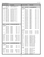

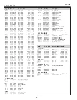

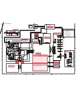

A3
SCH_KG8AC
HOT
COLD
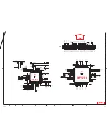
POWER
LAMP BALLAST
A/V
CW SENSOR
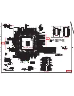
MAIN
DMD MODULE
FILTER
FAN NET
TEMP SENSOR1
TEMP SENSOR2
KEY
CW
(ROOM)
(DMD)
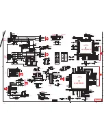
P.F CONTROL
MR4010-7101
IC631
FA5550NG
IC621
TA76L431FBP
IC671
D
D
POWER FACTOR CORRECTION
PROJECTION LENS
D
D
D
E
E
D
D
D
1AV4M10B50400
FN901
1AV4M10B50500
FN902
1AV4M10B50501
FN903
1AV4M5B48102
FN904
1AV4M10B50400
FN905
1AV4M10B50502
FN906
1LB4A10B12700
SP901
CO
M
NO
NC
1AV4S10B8270N
SW901
1
2
3
J10XC300G
K96A
1
1
2
2
3
4
5
6
7
8
9
10
11
12
13
14
15
16
17
18
19
20
21
22
23
24
25
26
27
28
29
29
30
30
J10XE300G
K96B
1
1
2
2
3
4
5
6
7
8
9
10
11
12
13
14
15
16
17
18
19
20
21
22
23
24
25
26
27
28
29
29
30
30
J10EP121G
K8A
1
1
2
3
4
10
5
11
6
12
12
7
8
9
J10QG505G
K8B
20
21
22
23
24
25
1
1
26
2
2
27
3
28
4
29
5
6
7
8
9
30
31
32
33
34
35
36
37
38
39
40
41
42
43
44
45
10
46
11
47
12
48
13
49
49
14
15
16
17
18
19
50
50
J10ES036G
K8F
1
1
2
3
3
J10QF045G
K8H
1
4
J10ES056G
K8E
1
5
J11RC043G
K8D
1
4
AC CORD
W901
AC100-120V
AC100-240V
CN2
1
5
CN3
1
2
3
4
J10ES046G
K8C
1
4
S40B0170N
SW902
1
2
LAMPDC_ON
POWER_SW_A
ES16V
P5
V
OUT_A
CWINDEX
OUT_B
OUT_C
CWCTR
1
2
3
4
CN1
1
2
3
4
CN4
1
2
3
4
SDA2
SCL2
SDA2
SCL2
P3P3V
P3P3V
FAN_LOCK
FAN1
P5V
J10QF045G
K88H
1
4
J10ES056G
K88E
1
5
J10EG045G
K67A
1
4
GND
OUT
VCC
R/C PRE AMP
LAMP_LED
1/16GJ
100A
R2811
02DZ12YG
D2812
TEMP_LED
X
R2813
1/16GJ330A
R2823
02DZ12YG
D2821
SML-521MUWG
D2818
READY
(RED)
POWER ON
(GREEN)
1
2
RED
3
GREEN
4
AH
Q2812
AH
Q2816
X
R2828
SMLE12BC7TG
D2811
3D
(BLUE)
X
R2821
1/16GJ
180A
R2826
1/16GJ180A
R2819
1/16GJ180A
R2827
1/16GJ
180A
R2818
SMLE12Y8WG
D2813
LAMP REPLACE
(YELLOW)
SMLE12V8WG
D2816
TEMP WARNING
(RED)
AH
Q2811
02DZ12YG
D2819
AH
Q2813
1/16GJ
180A
R2814
X
R2817
02DZ12YG
D2817
1/16GJ180A
R2816
POWER_LED
3D_LED
READY_LED
1/16GJ100A
R2812
AH
Q2814
X
R2824
1/16GJ
330A
R2822
02DZ12YG
D2814
S10B3530G
SW6806
UP
1
2
3
4
S10B3530G
SW6811
KEYSTONE
1
2
3
4
S10B3530G
SW6802
RIGHT
1
2
3
4
S10B3530G
SW6807
SELECT
1
2
3
4
S10B3530G
SW6804
DOWN
1
2
3
4
S10B3530G
SW6803
LEFT
1
2
3
4
S10B3530G
SW6808
MENU
1
2
3
4
S10B3530G
SW6809
SETUP
1
2
3
4
S10B3530G
SW6801
POWER
1
2
3
4
KEYSTONE
1/16GZ0A
R6816
DOWN
SETUP
1/16GZ0A
R6806
MENU
1/16GZ0A
R6803
1/16GZ0A
R6811
LEFT
1/16GZ0A
R6808
SELECT
1/16GZ0A
R6818
RIGHT
UP
1/16GZ0A
R6813
1/16GZ0A
R6821
P0WER
1/16GZ0A
R6801
1/16GJ
100A
R2802
U20C47500
A2801
1
2
3
X
D2801
KK470MN
C2803
1/16GJ47A
R2801
X
D2802
6.3KM47PCH
C2802
10KK1MN
C2801
K68A_19
K68A_27
RIGHT
16KK
0.1MN
C6801
READY_LED
SELECT
K68A_G1
LAMP_LED
K68A_17
UP
TEMP_LED
P0WER
DOWN
K68A_23
3D_LED
K68A_G2
R/C
KEYSTONE
POWER_LED
SETUP
J10XC300G
K68A
1
1
2
2
3
4
5
6
7
8
9
10
11
12
13
14
15
16
17
18
19
20
21
22
23
24
25
26
27
28
29
29
30
30
K68A_21
K68A_15
MENU
RC3.3V
LEFT
R/C
K68A_11
K68A_10
K68A_9
K68A_8
K68A_7
K68A_6
K68A_5
K68A_4
K68A_3
K68A_29
16KK
0.1MN
C2811
RC3.3V
RC3.3V
1SS352G
D7702
1/16GJ10KA
R7702
FAN2
P5V
16KK
0.1MN
C7702
L26B
3470G
L7702
1/16GJ10KA
R7703
L26B
3470G
L7703
FAN3
1SS352G
D7703
16KK
0.1MN
C7703
P5V
FAN4
P5V
16KK
0.1MN
C7704
1SS352G
D7704
1/16GJ10KA
R7704
L26B
3470G
L7704
FAN5
P5V
16KK
0.1MN
C7705
1SS352G
D7705
1/16GJ10KA
R7705
L26B
3470G
L7705
1/16GJ10KA
R7706
L26B
3470G
L7706
FAN6
1SS352G
D7706
16KK
0.1MN
C7706
P5V
FAN2
FAN6
FAN4
FAN1
FAN3
FAN5
J10EP032G
K00A
AUDIO
1
1
2
3
3
SP-
SP+
FAN_LOCK
RC3.3V
READY_LED
LAMP_LED
TEMP_LED
3D_LED
POWER_LED
L26B3470G
L701
16KK
0.1MN
C701
L3CZ220PG
L702
L3CZ220PG
L703
L3CZ220PG
L704
L3CZ220PG
L706
L3CZ220PG
L707
DOWN
KEYSTONE
SETUP
MENU
LEFT
RIGHT
SELECT
UP
POWER
R/C
K07A_3
K07A_1
K07A_5
K07A_7
K07A_9
K07A_11
K07A_13
K07A_15
K07A_17
K07A_19
K07A_20
K07A_23
K07A_25
K07A_27
K07A_31
K07A_41
K07A_42
K07A_48
K07A_40
K07A_29
K07A_49
K07A_44
K07A_37
K07A_G1
K07A_G2
K00A-G
K07B_27
K07B_15
K07B_G2
K07B_17
K07B_19
K07B_21
K07B_23
K07B_G1
K77C-1
K77C-2
K77C-G
K77B-1
K77B-G
K77B-2
K77D-1
K77D-G
K77D-2
K77E-1
K77E-G
K77E-2
K77F-1
K77F-G
K77F-2
K07A_43
J10EX052G
K47A
BALLAST
1
RXD
GND
5V
ON/SYNC
5
TXD
BALLAST_RXD
BALLAST_TXD
LAMP_SYNC
P5V
L26B3470G
L4752
L3CZ220PG
L4751
L3CZ220PG
L4753
L3CZ220PG
L4754
L3CZ220PG
L4756
X
R4751
16KK0.1MN
C4751
K47A-3
K47A-1
K47A-5
K47A-4
K47A-G
K47B-2
K47B-1
K47B-G
K07A_33
K07A_35
K07A_39
K07A_47
K07A_45
POWER_LED
POWER
FAN2
3D_LED
SP-
KEYSTONE
FAN6
BALLAST_RXD
DOWN
READY_LED
J10QG505G
K07A
20
21
22
23
24
25
1
1
26
2
2
27
3
28
4
29
5
6
7
8
9
30
31
32
33
34
35
36
37
38
39
40
41
42
43
44
45
10
46
11
47
12
48
13
49
49
14
15
16
17
18
19
50
50
LAMP_SYNC
UP
FAN3
BALLAST_TXD
LEFT
FAN_LOCK
LAMP_LED
MENU
FAN4
RIGHT
RC3.3V
TEMP_LED
FAN1
SELECT
P5V
FAN5
R/C
SETUP
SP+
J10XC300G
K07B
TO:KEY UNIT
1
1
2
2
3
4
5
6
7
8
9
10
11
12
13
14
15
16
17
18
19
20
21
22
23
24
25
26
27
28
29
29
30
30
J10ES046G
K77B
FAN2
1
4
J10ES036G
K77E
FAN5
1
1
2
3
3
J10QF035G
K77D
FAN4
1
1
2
3
3
J10QF045G
K77C
FAN3
1
4
J10ES056G
K77F
FAN6
1
5
J10EG025G
K47B
COVER SW
1
2
SCREW_14
X
SCREW71
1 2
3 4 5 6 7
8 9 10 11 12 13 14
SCREW_14
X
SCREW73
1 2
3 4 5 6 7
8 9 10 11 12 13 14
SCREW_14
X
SCREW74
1 2
3 4 5 6 7
8 9 10 11 12 13 14
SCREW_14
X
SCREW72
1 2
3 4 5 6 7
8 9 10 11 12 13 14
J30B1640G
TPFAN1
J30B1640G
TPFAN2
J30B1640G
TPFAN3
J30B1640G
TPFAN4
J30B1640G
TPFAN5
J30B1640G
TPFAN6
J30B1640G
TPFANGND
Z30B0220G
SC002
1
2
Z30B0220G
SC001
1
2
2
S16V
1
Z/C
FB
GND
VCC
EM
Vin
CC
D611E
D611F
Z21B
1630N
Z21B
1630N
LAMPDC_ON
POWER_SW_MCU
SW_IC_VCC
1SS352G
D613
GND
1SS352G
D612
2000KK
470NH
C632
1/10GJ68C
R625
1/10GJ3.9KC
R671
1/10GJ270KC
R629
1/10GJ18KC
R648
5XJ0.15VBE
R685
GND
1/10GJ
47KC
R617
L26B5410N
L612
1
2
3
4
RF101L2SP
D651
1/3GJ680
R686
1/10GJ10KC
R628
FMX-G26S
D611
1/10GF6.8KC
R674
1/10GJ10KC
R627
1/10GJ
10KC
R651
F35B1470N
L611
450GK1BS
C614
TLP781F-GBP
PC663
1
2
3
4
1
FB
2 COMP
3 MUL
4
IS
5
SLOPE
6
GND
7
OUT
8
VCC
1SS352G
D631
GND
Z20051---
L613
Z20051---
L661
EG01C
D666
1/10GZ0C
R633
25EM1005D
C673
2SK3934LBS
1
Q61
2
G
D
S
TLP781F-GBP
PC671
1
2
3
4
Z20051---
L614
1000KK
1000NH
C611
1/10GJ330C
R662
RF101L2SP
D632
GND
GD680KB
R616
AH
Q642
ZZ0122
L631
1/10GJ68K
C
R642
1/10GJ
11KC
R631
DHXAVB002
PTH611
GND
AH
Q641
1/10GF5.1KC
R673
1/10GJ
47KC
R613
1/10GJ4.7KC
R675
1/10GJ22K
C
R
63
6
25EM18005F
C661
GND
1/10GJ33KC
R634
GD680KB
R615
1/2GJ22
R652
2SK3934LBS
1
Q61
1
G
D
S
1/10GJ220C
R624
1/10GJ
10KC
R643
1/10GJ1KC
R672
2SK4085LS
Q643
1/10GJ68C
R620
UDZS8.2BG
ZD631
1/10GJ33C
R619
1/2GJ
82K
R689
1/10GJ18KC
R646
1/10GF2.2KC
R676
GND
1/10GJ33C
R626
EG01C
D633
AK
Q651
1/2GJ
82K
R690
YG862C10R
D661
1NJ0.39E
R635
1000KK
1000NH
C612
DDXAVB029
DB611
1
2
3
4
7
1
2
3
4
5
9
TLP781F-GBP
PC661
1
2
3
4
J10AV123N
K6R
1
1
2
3
4
5
6
7
8
9
10
11
12
12
AH
Q621
1/10GJ18KC
R637
1/10GJ47K
C
R
63
8
AH
Q622
1/2GJ
82K
R691
1/2GJ
82K
R665
630GJ0.01FD
C674
CEXAVB
01100
C615
25EM18005F
C663
1GK680VB
R687
1/2GZ0
R704
1/10GJ220C
R692
GJ680KB
R618
GJ680KB
R632
1/8GZ000
R707
K6A_1B
K6A_1A
K6A_2A
K6A_2B
1/2GZ0
R711
1/2GZ0
R712
T651H1
T651H3
T651H7
T651H12
DB611H1
DB611H4
DB611H3
DB611H2
D611H1
D611H2
L612H2
L612H1
L611H1
L611H2
Q612HS
Q612HD
Q611HS
Q611HD
C615H1
C615H2
PTH611H1
PTH611H2
T651H6
VCC
IC621VCC
FB
Z/C
EM
CC
VIN
K6R_1
K6R_2
K6R_3
K6R_7
K6R_8
K6_10
K6R_9
C615_A
C615_B
seiryu-
K6C_2A
K6C_2B
K6C_1B
K6C_1A
IC621FB
T651H11
L612H3
L612H4
TP_L612_4
TP_L612_3
5XJ0.15VBE
R614
25EM1005D
C672
1/10GJ10KC
R641
D665H2
D665H1
Q611HG
Q612HG
D665H3
35EM2205D
C651
DHXAVB032G
PTH641
J10EM024N
K6C
1
2
1/2GZ0
R701
1/10GD
620C
R622
1/10GD
8.2KC
R621
1/3GJ360K
R611
1/3GJ430K
R612
KK0.01GQ
C625
25KK11
D
C626
16KK0.47GQ
C621
KK0.047GQ
C622
KK0.01GQ
C623
KK2200GQ
C627
25KK4.7BB
C644
KK0.1GQ
C
65
4
CJ1000CGQ
C
63
3
CJ220CGQ
C631
KK2200G
Q
C634
KK0.1GQ
C641
CJ1000CG
Q
C629
KK0.1G
Q
C653
KK0.1G
Q
C662
KK0.1GQ
C671
1/10GJ10KC
R644
1/8GZ000
R703
1/8GZ000
R702
L51B7400N
T651
2
3
5
6
7
8
9
11
1
12
FFXAVB009SGJ
F631
1/2GZ0
R721
2EAF0208--
PB601A
1 2
3
2HEA0344C-
DB611H
1 2
1/10GZ0C
R623
DTXAVB002
D665
K6_11
450GK1BS
C613
AC100-120V
(NEUT)
F601
6.3A250VTS
F.G.
(NEUT)
(LIVE)
AC100-240V
(LIVE)
250KK1500XH
C60
3
K602_1B
K602_1A
SCB1
1
2
3
4
5
6
7
8
9
10
11
12
13
14
K602_2B
L601H1
K602_2A
L601H2
L601
F35B1010N
1
2
3
4
L601H3
L601H4
J11B8790N
K601
1
2
3
LF601_2A
LF601_1A
K601H2
K601H1
SCB2
1
2
3
4
5
6
7
8
9
10
11
12
13
14
J20B0040N
F601
1/3GJ360K
R600
1/3GJ430K
R601
250KK2200XH
C60
8
250KK2200XH
C60
7
275GK
0.33VBBC
C601
275GK
0.33VBBC
C602
275GK
0.33VBBC
C605
250KK1500XH
C60
4
DVXAVB013
VA601
1
2
J10B1010N
K602
1
2
L602H1
L602H3
L602H4
L602H2
L602
F35B1010N
1
2
3
4
K40A
K35C
LP900
ECO
LAMP_SW
LAMP_DET
GND
5V
A901
THERMOSTAT SW
81N83K2R0
SW902A
SW902B
81N83K2R0
INTAKE FAN
OF LAMP (TOP PART)
INTAKE FAN
OF LAMP (BOTTOM PART)
EXHAUST FAN
OF LAMP
EXHAUST FAN
OF POWER BOX
INTAKE FAN
OF COLOR WHEEL
INTAKE FAN
80X80X25
10W 8ohm
53X43-21
1AA9HDFBE300Z
Z07B&68A
1AA9KBABE280Z
Z8B&97A
1AA95AYBE100Z
Z8E&88E
Z8H&88H
1AA94BGAF100Z
1AA9HDFBE100Z
Z96B&96A
Z8C&67A
1AA95AYBE200Z
Z47A&CN2
1AA95BFBE1408
1AA9CBGAC120Z
Z6R&8A
1LB9W03BC006A
K6A&CN1
A901A
1AA4W30B50002
1
2
3
4
5
6
7
8
9
10
11
12
13
14
15
16
A
B
C
D
E
F
G
H
I
J
K
L
A
B
C
D
E
F
G
H
I
J
K
L
KG8AC-01
E
D
S
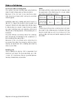
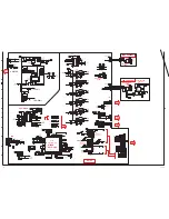
Power Failure, Fan Failure Detection Signals
- NO POWER when one of those signals detects a failure.
電源異常、ファン異常検出信号
- 異常検出でスタンバイになります
Power Drive, Fan Drive Signals
- NO POWER when one of those signals has a failure.
電源ドライブ、ファンドライブ信号
- 異常発生でスタンバイになります
Switch Signals [AV switch, Mute, etc]
- NO PICTIER or NO SOUND when one of those signals
has a failure.
各種スイッチ信号(AV切替、ミュートなど)
- 異常発生で映像出ず、音声出ずになります
Indication of Signals /
信号の表示について
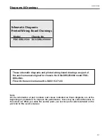
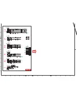
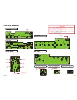
Schematic Diagrams
CAutION
Components indicated by a mark
!
in this schematic diagram have
the special significance in the safety. It is therefore, particularly rec-
ommended that the replacement of those parts must be made by
exactly the same parts. Must be used with a specified fuse. Unau-
thorized substitutions may result in fire or accident.
This projector is isolated from AC line by using the internal converter
transformer. Please pay attention to the following notes in servicing.
1. Do not touch the part on hot side (primary circuit) or both parts on
the hot and cold sides (secondary circuit) at the same time.
2. Do not shorten the circuit between hot and cold sides.
3. The grounding lead must be connected to the ground of the same
circuit when measuring the voltages and waveform.
注 意
!
印の部品は、安全上重要な部品です。交換をするときは安全および性能
維持のため必ず指定の部品をご使用ください。
ヒュ−ズは必ず指定品番のものをご使用ください。指定品番以外のヒュ−ズを
使用しますと事故や、火災の原因となります。
本機は充電部と非充電部のア−スが異なりますので下記の事項にご注意くだ
さい。
1.充電部に触れたり、充電部と非充電部に同時に触れると感電することが
あります。
2.充電部、非充電部の間を短絡しないでください。故障の原因になります。
3.測定器をつなぐ際、ア−スは測定点と同じ回路のア−スから取ってくださ
い。
充電部
非充電部
Summary of Contents for PDG-DWL2500 - 2500 Lumens
Page 47: ... 47 IC Block Diagrams LV49152V Audio Output IC001 LC87F2G08A Sub Micom IC4501 ...
Page 48: ... 48 IC Block Diagrams M62393 DAC IC7881 MR4010 Power Switching IC631 ...
Page 49: ... 49 IC Block Diagrams PIC18F67J60 Network IC8301 NJW1156 Audio Selector IC5101 ...
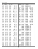
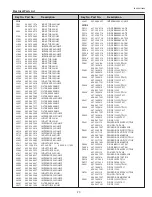
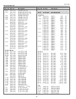
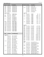
Page 83: ...Key No Part No Description Key No Part No Description 83 Electrical Parts List KG8 DWL250000 ...
Page 84: ... KG8AC July 2010 DC 50 Printed in Japan SANYO Electric Co Ltd ...