Sanyo MCD-X75L, Service Manual
The Sanyo MCD-X75L offers high-quality audio experience with its advanced features and sleek design. Enhance your music journey by accessing the Service Manual, a comprehensive and detailed manual that can be downloaded for free from manualshive.com, allowing you to fully optimize this exceptional product.
Share
Download


Reviews:
No comments
Related manuals for MCD-X75L
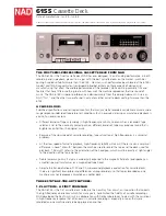
6155
Brand: NAD Pages: 3

CD555
Brand: NAIM Pages: 18
YP-R2CB
Brand: Samsung Pages: 59

AZ6828/17
Brand: Magnavox Pages: 2

172.715
Brand: Power Dynamics Pages: 28

USB-PRO
Brand: easyonHold Pages: 4

PMP281-8
Brand: Polaroid Pages: 14

B4359
Brand: Fisher-Price Pages: 4

Caspian M2
Brand: Roksan Audio Pages: 2

Cl 580
Brand: NAD Pages: 6

PDV-701S
Brand: Hitachi Pages: 36

PDV-1021S
Brand: Hitachi Pages: 37

AZ787
Brand: Philips Pages: 3

ARP-006-O
Brand: Pioneer Pages: 47

AZ787
Brand: Philips Pages: 17

AZ 1020
Brand: Philips Pages: 2

AX7201
Brand: Philips Pages: 2

AX7201
Brand: Philips Pages: 2


