background image


3. MAINTENANCE 


3-1 LMU-TK18AG2 

Disassembling the major components 
 

(1) Cabinet 

1.Unscrew to secure the cabinet (10-position) 
2.Pull the cabinet upward to remove it 


(2) LCD Panel 

1.Unscrew to secure the LCD Panel (4-position) 
2.Pull the LCD Panel and pull two connectors out from inverter unit 
3.Disconnect two cables from the Main PCB 
4.Unscrew to secure the earth terminal (1-position) 


(3) Main PCB 

1.Pull a RGB signal cable out 
2.Unscrew to secure the Main PCB (7-position) 
3.Disconnect the cables on the Main PCB (7-position) 
 

/ Two connectors from the LCD Panel 


/ One connector from the Switch PCB 


/ One connector from the VR PCB 


/ One connector from the DC-IN PCB 


/ Two connectors from the Inverter PCB on LCD 

4.Unscrew to secure the bracket for RGB connector (2-position) 


(4) Driver PCB 

1.Unscrew to secure the Driver PCB (2-position) 
2.Disconnect the cable from the Inverter PCB 
3.Disconnect the cable from the DC-IN PCB 


(5) Connector PCB 

1.Unscrew to secure the Connector PCB (2-position) 
2.Disconnect the cable from the Main PCB 


(6) VR PCB 

1.Unscrew to secure the VR PCB (2-position) 
2.Disconnect the cable from the Main PCB 


(7) DC-IN PCB 

1.Unscrew to secure the DC-IN PCB (2-position) 
2.Disconnect three cables, one from power switch, one from Driver PCB and 

one from the Main PCB 


(8) Power Switch 

1.Remove the power switch, while pressing the hook of the power switch 


- 6 -

Summary of Contents for LMU-TK18AG2

Page 1: ......

Page 2: ...6 3 2 LMU TK18AG2TC 7 4 BLOCK DIAGRAM 8 5 CONNECTION DIAGRAM 9 6 TABLE OF SIGNAL NAME 10 11 7 EXPLODED VIEW AND PARTS LIST 7 1 Exploded View 12 7 2 Parts List 7 2 1 LMU TK18AG2 13 7 2 2 LMU TK18AG2TC 14 8 APPENDEX 15 Refer to the separate volume User s Manual and CD ROM that included for instruction 1 ...

Page 3: ...s the unit unplug the AC power cord immediately DO NOT PLUG IN THE UNIT AGAIN Handling precautions l Avoid bending kinking or damaging the AC power cord l Never insert or remove the power cord with wet hands Also be sure to hold cord by the plug when removing it from the outlet l Do not remove any parts that are held in place with screws The unit does not contain any user serviceable items l Maint...

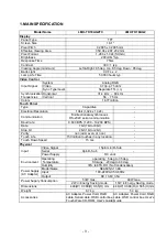
Page 4: ...synchronous RS 232C serial communication Baud rate 9 600 BPS 1 200 19 200 BPS Data 7 bit 7bit or 8bit Stop bit 2 bit 1bit or 2bit Parity non odd even or non Touch Life 150 million touches in any location Touch Down Speed 15 ms Physical Video Signal 15pin mini D Sub Serial 9pin D Sub Input Power Supply DC Jack operating 5 deg to 35 deg Operating Temperature Storage 20 deg to 60 deg Environment Humi...

Page 5: ...tive Replace a LCD module with the new one C 12 Is the Inverter block on LCD module defective Replace a LCD module with the new one C 13 Is the DC DC Conv PCB defective Replace a DC DC Conv PCB with the new one C 14 Is the display circuit on main PCB defective Replace the main PCB with the new one C 15 Is the Power Supply circuit on main PCB defective Replace the main PCB with the new one C 2 1 Is...

Page 6: ...tly A 2 Is a signal cable connected securely Check the connection of a signal cable A 3 Is a sigil cable extended Don t extend a signal cable A 4 Is the output level on image from a computer not agreeable to LCD s specification Check the specification of a computer B 5 Is the Image Processing circuit on main PCB defective Replace the main PCB with the new one C 9 1 Is a signal cable connected secu...

Page 7: ... the Switch PCB One connector from the VR PCB One connector from the DC IN PCB Two connectors from the Inverter PCB on LCD 4 Unscrew to secure the bracket for RGB connector 2 position 4 Driver PCB 1 Unscrew to secure the Driver PCB 2 position 2 Disconnect the cable from the Inverter PCB 3 Disconnect the cable from the DC IN PCB 5 Connector PCB 1 Unscrew to secure the Connector PCB 2 position 2 Dis...

Page 8: ...ector from the DC IN PCB Two connectors from the Inverter PCB on LCD One connector from the Touch Controller PCB 4 Unscrew to secure the bracket for RGB connector 2 position 4 Driver PCB 1 Unscrew to secure the Driver PCB 2 position 2 Disconnect the cable from the Inverter PCB 3 Disconnect the cable from the DC IN PCB 5 Touch Controller PCB 1 Unscrew to secure the Touch Controller PCB 2 position 2...

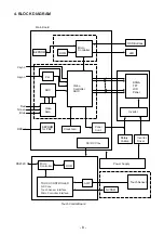
Page 9: ... ROM Video Amp SXGA TFT LCD Panel ADC EEPROM for P P Clock Gen Rotary Volume Inverter Touch Control Board Touch Senser DC DC Conv Inverter Driver Power Supply AMP TOUCH CONTROLLER ROM Micro Controller NVRAM A D Conv Touch Senser Interface Micro Controller Interface Panel Cont Main Board 4 BLOCK DIAGRAM 8 ...

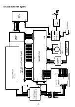
Page 10: ... C N C GND GND DAO DAO GND DA1 DA1 GND DA2 DA2 GND CKA DA3 GND CKA DA3 GND N C PWSEL GNDB BRTP BRTL BRTH BRTC N C N C GNDB 13 5V GND GNDB GNDB GNDB GNDB VDDB VDDB VDDB VDDB N C N C CN201 1 2 3 4 5 6 7 8 9 10 11 12 13 14 15 16 17 18 19 20 21 22 23 24 25 26 27 28 29 30 CN301 1 2 3 4 5 6 7 8 CN2 1 2 3 4 5 6 7 8 9 10 11 12 13 14 15 16 17 18 19 20 21 22 23 24 25 26 27 28 29 30 CN203 1 2 CN100 8 15 7 14...

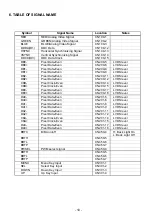
Page 11: ...l CKB Pixel Clock Even CN200 15 LVDS level DB3 Pixel Data Even CN200 17 LVDS level DB3 Pixel Data Even CN200 18 LVDS level DA0 Pixel Data Even CN201 5 LVDS level DA0 Pixel Data Even CN201 6 LVDS level DA1 Pixel Data Even CN201 8 LVDS level DA1 Pixel Data Even CN201 9 LVDS level DA2 Pixel Data Even CN201 11 LVDS level DA2 Pixel Data Even CN201 12 LVDS level CKA Pixel Clock Even CN201 14 LVDS level ...

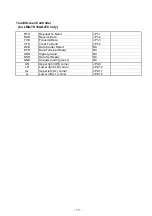
Page 12: ...D Transmit Data JP1 3 CTS Clear To Send JP1 4 DCD Data Carrier Detect NC DTR Data Terminal Ready NC GND Signal ground NC DSR Data Set Ready NC GND Chassis earth ground NC UR Upper right UR corner JP2 9 LR Lower right LR corner JP2 10 UL Upper left UL corner JP2 11 LL Lower left LL corner JP2 12 11 ...

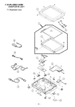
Page 13: ...7 EXPLODED VIEW AND PARTS LIST 7 1 Exploded view 12 ...

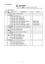
Page 14: ...298 2376 POLYETHYLENE BAG 1 FOR CNT BOX 632 607 4824 POLYETHYLENE BAG L 180X270 1 FOR USER S GUIDE 632 567 2588 POLYETHYLENE BAG 200X300 1 FOR RGB CABL ACCESSORY 661 006 5903 INSTRUCTION MANUAL ENGLISH 1 CABINET1 1 661 012 7915 CABINET ASSY 1 13 661 006 5958 RATING PLATE 1 CHASSIS 11 661 012 7922 CHASSIS ASSY BOTTOM 1 CHASSIS ELC 4 661 012 7939 LCD ASSY 1 16 661 012 7946 AC ADAPTER ASS Y 1 2 661 0...

Page 15: ... 2588 POLYETHYLENE BAG 200X300 1 FOR RGB CABL 632 607 4824 POLYETHYLENE BAG L 180X270 1 FOR SERIAL CABLE ACCESSORY 661 006 5903 INSTRUCTION MANUAL ENGLISH 1 632 867 2325 CD ROM DISK TOUCHWARE 1 CABINET1 1 661 012 9087 CABINET ASSY 1 13 661 006 5989 RATING PLATE 1 CHASSIS 11 661 012 9094 CHASSIS ASSY BOTTOM 1 CHASSIS ELC 4 661 012 9100 LCD ASSY 1 3 661 012 9131 TOUCH SENSOR ASSY 1 5 661 012 9148 SE...

Page 16: ...APPENDIX Version of Firmware The Version of Firmware is displayed on screen Turn the Power Switch to OFF While pressing of the ENTER button turn the Power Switch to ON 15 ...

Reviews: