12
amplifier BH3547F amplifying, then output two ways. One way will be sent to earphone, another
way will be sent to digital sound amplifier R2A15112FP amplifying then sent to speaker.
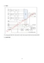
5. HDMI signal flow
Three HDMI video signals via switcher PS321 are directly fed to the master control IC MSD109 to
digital decode, image scale and OSD superposition, then output LVDS drive level for panel display.
HDMI audio signal via decoder built-in MSD109 is fed to back end to bass adjust and volume
control, the sound will separate into L/R channels and input to earphone amplifier BH3547F
amplifying, then output two ways. One way will be sent to earphone, another way will be sent to
digital sound amplifier R2A15112FP amplifying then sent to speaker.
Block diagram
Summary of Contents for LCD-32XR8DA
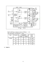
Page 18: ...16 6 TDA1616 ...
Page 19: ...17 ...
Page 26: ...data process ...
Page 27: ...data process ...
Page 28: ...data process ...
Page 29: ...data process ...
Page 30: ...data process ...
Page 31: ...data process ...
Page 32: ...data process ...
Page 33: ...data process ...
Page 34: ...32 power ...
Page 35: ...42 power ...
Page 36: ...IR key ...
Page 38: ...1 2 3 5 6 7 8 4 9 LCD 32XR8DA ...
Page 42: ...LCD 42XR8DA ...
Page 45: ...June 2008 ...

