background image

6

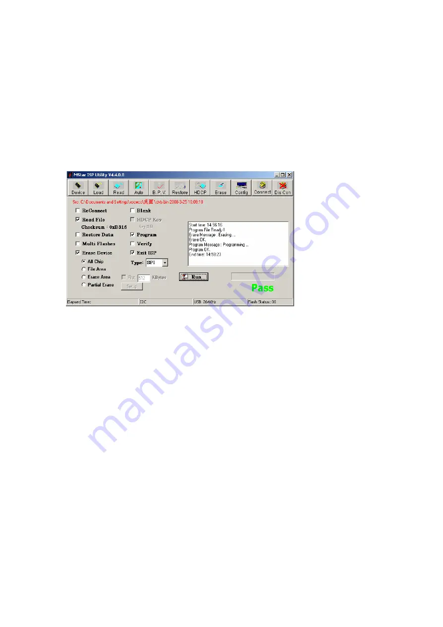
 Press “Run” shown as Fig. 4 to perform upgrading in two steps, “Erase” and “Program”; 

Normal upgrading process: 

The first step “Erasing…

  Flash Status: 03” will last for some time, or erasing is failed if the step   

passes over immediately; please confirm procedure 2) to perform upgrading again; 

The second step is “Programming…

Flash Status:00”; 

Then prompt “Pass” displays; 

7

 Prompt “Pass” will display by button “Run” when upgrading succeeds; please refer to Fig. 6;          


Fig. 6 Prompt “Pass” displayed by “Run” when upgrading succeeds 

8

 Need not exit ISP upgrading interface if there are other TV sets to be upgraded , only procedures 

3) and 6) need repeat;   

Note 3   

Upgrading with USB: 

1

 Make sure U disk is formatted as FAT32; 

2

 Copy software file named as “Merge. bin” to U disk; 

3

 Turn on the TV set, then insert U disk in USB port of the unit; 

a)  First press key “

INPUT

”, then press keys “

2

5

8

0

” in turn to enter into primary factory 

menu; 

b)  Choose “USB SW Update” to begin upgrading; 

4

 Upgrading  processes: 

A

Read data from U disk while data indicator light of U disk is twinkling at the same time; 

B

Upgrading flash, then the unit will be in “standby” mode;   

5

 Cut off the power supply and then restart the TV set, enter into factory menu to verify version and 

time parameter, then perform “EEPROM Init” to complete the whole upgrading processes. 

Note: The USB upgrading method can not be sure to be suitable for all kinds of U disk, so try another U 

disk if necessary. 

Summary of Contents for LCD-32XR11F

Page 1: ...SERVICE MANUAL PRODUCT CODE No 1 682 350 97 PAL B G Australia FILE NO PRODUCT CODE No REFERENCE No SM0915189 LCD 32XR11F NTSC AV LCD TV INPUT ...

Page 2: ...upgrade instructions Working principle analysis Block diagram IC block diagram Wiring diagram Troubleshooting flow chart Schematic diagram APPENDIX A Assembly list APPENDIX B Exploded View 3 5 12 15 17 18 21 22 25 Assembling the Stand WALL MOUNTING INSTRUCTIONS ...

Page 3: ... bad effect will result 2 5 If any foreign substance such as water liquid metal slices or other matters happens to fall into the module be sure to cut the power off immediately and do not move anything on the module lest it should cause fire or electric shock due to contact with the high voltage or short circuit 2 6 Should there be smoke abnormal smell or sound from the module please shut the powe...

Page 4: ...n range 20 80 Storage range 10 90 2 13 Display of a fixed picture for a long time may cause a permanent after image on the screen as commonly called ghost shadow The degree of the after image varies with the maker of LCD screen This phenomenon doesn t represent failure This ghost shadow may remain in the picture for a period of time several minutes But when operating it please avoid displaying sti...

Page 5: ...nts Multimeter or oscilloscope VG 849 CA 210 USB storage device DVD HDMI 1 4 supported or equipments with the same functions 3 Adjustment Processes 3 1 Power voltage checking According to the wiring diagram specified by Product Specification connect power board assembly data processing assembly IR Key board assembly backlight board assembly correctly supply with power press button to power on the ...

Page 6: ...justment Input central signal check TV function omitted channel analog parameters control etc check earphone speakers output Input Component signal check YPbPr functions Input D SUB signal check display and all functions such as analog parameter H V center etc Check AV input output and relevant functions Default settings before ex factory Check USB multimedia port and Check accessory and packing C...

Page 7: ...setting could not change if central signal setting has any modification so please search for digital program manually by perform item DTV of menu Channel k Factory menu item Color Temp to be used for white balance adjustment l Factory menu item Store Setting Init m Factory menu item USB SW Update to be used for software updating from USB port when U disk containing updating software is inserted in...

Page 8: ...rn 921 16 step Gray move cursor to item MODE press keys and to choose item HDMI then move cursor to item TEMPERTURE and press keys and to choose COOL e Fix G GAIN adjust R GAIN B GAIN to set 14th chromatic coordinates as 272 278 f Fix G OFFSET adjust R OFFSET B OFFSET to set 4th chromatic coordinates as 272 278 g To make sure chromatic coordinates of bright scale are X 272 10 Y 278 10 and chromati...

Page 9: ...isplay 5 2 AV port Input AV signal with formats listed as Table 1 separately check picture sound and other functions Table 1 AV video signal formats No Lines per frame H Freq kHz V Freq Hz Note 1 525 15 734 15 75 59 94 60 NTSC NTSC4 43 PAL60 PAL M 2 625 15 625 50 PAL PAL N SECAM 5 3 Component port Input Component signal from VG 849 with formats listed as Table 2 separately check picture and sound ...

Page 10: ...768 60 023 75 029 78 75 VESA 12 1152 864 67 5 75 108 VESA 13 1280 960 60 60 108 VESA 14 1280 1024 63 98 60 02 108 VESA 15 1280 1024 80 75 135 SXGA 16 1360 768 47 7 60 85 5 WXGA 17 1440 900 55 9 60 106 5 WXGA Panel National only 18 1680 1050 65 3 60 146 25 WSXGA Panel National only 19 1920 1080 67 5 60 148 5 5 5 HDMI port HDMI port supports all signal formats supported by Component port Table 2 and...

Page 11: ...ia formats as below Photo JPEG BMP PNG Video H 264 MPEG 1 MPEG 2 VC 1 FLV Audio WMA MP3 M4A AAC 5 7 Music port depending on different models whether contain the port or not Input audio signal to side music port analog audio input from audio output equipment check audio output 5 8 Other functions check a Check timing on off sleeping time off picture sound mode OSD stereo digital audio port etc b Ch...

Page 12: ...lease make sure option Config is ticked off during software upgrading and reset write protection after ALL 100 upgrading software is opened each time Note 2 Upgrading method with ISP upgrading instrument 1 Main board upgrading connect 4 core line of ISP to Debug port X603 on main board The Unit upgrading connect both VGA ports of ISP and main board enter into factory menu and set ISP Mode as ON 2 ...

Page 13: ...he first menu Device and choose MX25L64 manually then press Connect 4 Press Read choose upgrading file such as MERGE bin please refer to Fig 4 Fig 4 Choosing upgrading file 5 Press Auto tick off All chip program and other necessary options please refer to Fig 5 Fig 5 Options ...

Page 14: ...d 6 need repeat Note 3 Upgrading with USB 1 Make sure U disk is formatted as FAT32 2 Copy software file named as Merge bin to U disk 3 Turn on the TV set then insert U disk in USB port of the unit a First press key INPUT then press keys 2 5 8 0 in turn to enter into primary factory menu b Choose USB SW Update to begin upgrading 4 Upgrading processes A Read data from U disk while data indicator lig...

Page 15: ...r then LVDS signal is outputted to drive display panel Audio channel demultiplexing digital audio signal is processed by MSD309PX decoder and audio processor then double sound track analog audio signal stereo is outputted to MSD309PX to be processed by preamplifier acoustic effect processor and volume controller to get two parts of signals the analog part of signal is sent to earphone amplifier MA...

Page 16: ...w HDMI video signal is inputted to main chip MSD309PX to be processed by video decoder video processor and zoom controller then LVDS signal is outputted to drive display panel HDMI audio signal is sent to main chip MSD309PX to be processed by audio decoder pre amplifier acoustic effect processor and volume controller to get two parts of signals the analog part of signal is sent to earphone power a...

Page 17: ...RF MSD309PX LF VIF SIF HDMI1 w ARC HDMI2 HDMI3 VGA YPbPr Video In YPbPr Audio In VGA Audio In SPDIF IN AV Audio In RS 232 USB TAS5711 Audio Amplfier I2S LVDS DDR2 512Mbit X 2PCS Flash IR KEY POWER SUPPLY MAX232 Block Diagram ...

Page 18: ...Intermediate Frequency IF which is then sampled by an internal high resolution analog to digital converter A D for further processing The IF signals are filtered using a standard dependent high rejection channel filter and converted to a user programmable output frequency At the output of the D A converter the TV signal is low pass filtered using a high performance smoothing filter and input to a ...

Page 19: ... accepts a wide range of input data and data rates A fully programmable data path routes these channels to the internal speaker drivers The TAS5711 is an I2S slave only device receiving all clocks from external sources The TAS5711 operates with a PWM carrier between 384 kHz switching rate and 352 KHz switching rate depending on the input sample rate Over sampling combined with a fourth order noise...

Page 20: ...citors required by conventional single supply headphone amplifiers The MAX9820 features an undervoltage lockout that prevents over discharging of the battery During brownout conditions click and pop suppression that eliminates audible transients on startup a low power shutdown mode and thermal overload and short circuit protection Additionally the MAX9820 suppresses RF radiation received by input ...

Page 21: ...Main Board Key IR AMP Power LVDS Key Board IR Board Power Board Panel TCON Inverter Panel X503 X501 X502 X508 X601 X401 XV01 X604 X610 Debug X603 Wiring Diagram ...

Page 22: ...ck backlight board Check STANDBY circuits on power board Press key POWER on remote control or the unit check indicator Check if level of X601 PIN13 on main board is high Check if level of X601 PIN9 on main board is high Check power board Check if 5V is supplied to X601 PIN11 Check power control circuits on main board Check power control circuits on main board ...

Page 23: ...set by keys on remote control or the unit Do no channel have picture at all Enter into factory menu to initialize EEPROM then cut off main power and then turn on the TV set again check if there is picture Replace the main board Readjust the main board Press key MENU can OSD display normally ...

Page 24: ...19 25 are all high Check if level of VV03 b is low Check if there is signal inputted to NV01 PIN15 20 21 22 Check power voltage of NV01 Check IIS signal input circuits on main board Check Reset Mute circuits of power amplifier Replace VV03 Check 24V on power board Check IIC signal of NV01 PIN23 24 ...

Page 25: ...8 G1 VDDQ7 E9 VDDQ6 C9 VDDQ5 C7 VDDQ4 C3 VDDQ3 C1 VDDQ2 A9 VDDQ1 G8 DQ0 G2 DQ1 H7 DQ2 R1 VDD5 M9 VDD4 J9 VDD3 E1 VDD2 A1 VDD1 J7 VSSDL J1 VDDL H8 VSSQ10 H2 VSSQ9 F8 VSSQ8 F2 VSSQ7 E7 VSSQ6 D8 VSSQ5 D2 VSSQ4 B8 VSSQ3 B2 VSSQ2 A7 VSSQ1 P9 VSS5 N1 VSS4 J3 VSS3 E3 VSS2 A3 VSS1 C120 100n GND D GND D R108 10K R107 10K BL_PWM 003 B1 004 B5 ISP_EN 002 G1 KEY 003 C1 003 H4 LED 003 D1 1 CS 2 DO DQ1 3 WP DQ2...

Page 26: ... 12K RB37 10K CVBS1 RIN 001 F4 RB38 12K CB19 1u GND D RB32 33 RB23 33 RB24 33 RB26 33 GND D CVBS ROUT 001 F4 GND D GND D CVBS LOUT 001 F4 XB05 ST 113 R G2 L G5 001 F4 YPBPR LIN 10K RB17 12K RB16 GND D GND D 001 F4 YPBPR RIN 10K RB15 12K RB18 SPDIF 001 F5 002 D3 GND D RB25 0 CB10 1u CB11 1u CB49 1u CB50 1u HDMI2 SDA 001 E4 HDMI1 SDA 001 E5 HDMI3 SDA 001 E5 HP DCT 001 D5 3 3V CB17 180p CB18 180p CB3...

Page 27: ...K R694 1K R695 10K R696 10K R697 10K R698 4 7K R699 47K C715 100n V608 2SC4081 V609 2SC4081 3 3V 3 3V GND D C716 100n 5V_USB RV36 3K RV35 3K X610 1 2 R700 330 R701 330 V610 2SC4081 R702 4 7K R703 1K 5V S 3 3V S GND D 5V L615 STPB3216 380PT 5V R632 10K 1 R645 1K PWR_ON OFF 003 A2 003 A3 003 A4 003 B6 PWR_ON OFF 003 A2 003 A3 003 A2 003 B6 PWR_ON OFF 003 A3 003 A4 003 A2 003 B6 PWR_ON OFF 003 A2 003...

Page 28: ...XO3 001 D4 004 C5 RXOC 001 D4 004 C5 RXO1 001 D4 004 C5 RXO0 001 D4 004 C5 RXO2 001 D4 004 C5 RXO0 001 D4 004 D5 RXO3 001 D4 004 D5 RXO1 001 D4 004 D5 RXO2 001 D4 004 D5 RXOC 001 D4 004 D5 C232 120p C206 100p C207 100p R225 4 99K R230 100 C251 30p C253 30p R234 0 R236 0 R237 0 C248 100n C249 100n G201 31 875MHz N613 XC5200C 1 VDDA_1 2 IN1 3 GND_3 4 GND_4 5 GND_5 6 ExtChoke 7 GND_7 8 VDDA_8 9 VDDA_...

Page 29: ...Power board ...

Page 30: ...rocessing board XI6KI0040110 N101 N102 N106 N613 NV01 MSD309PX LF SV 5270309003 NT5TU32M16DG_AC 5273216001 XC5200C 5275200002 TAS5711 5275711001 IR board XI635KH01903 Key board XI635KS00300 Power board XI6KI00420B0 Remote control XI6010900802 RC 908 0A RC S071 Panel XI5203328308 T315HW04 VD ...

Page 31: ...APPENDIX B Exploded view LCD 32XR11F ...

Page 32: ...Display panel 5 Frame assembly 6 Power board assembly 7 Back cover assembly 8 Light guided pole 9 IR assembly 10 Speaker assembly 11 Data processing board assembly 12 Interface baffle right 13 Interface baffle down 14 Standing pole 15 Pedestal assembly Note Design and specification are subject to change without notice ...

Page 33: ... 1 8 XI570031901D Light guided pole 1 9 XI635KH01903 IR assembly 1 10 XI6170836000 Speaker assembly 1 11 XI6KI0040110 Data processing board assembly 1 12 XI5810P72110 Interface baffle right 1 13 XI5810V72200 Interface baffle down 1 14 XI58D0029200 Standing pole 1 15 XI6151212000 Pedestal assembly 1 16 XI6010900802 Remote control 1 17 XI5944039280 User manual 1 18 XI60Z0000741 Logical board 1 19 XI...

Page 34: ...a cabinet or other flat surface If you intend to mount your TV on a wall or other vertical surface you must remove the stand column If the stand is provided please read these instructions thoroughly before attempting this installation NOTE The appearance of this product in these illustrations may differ from your actual product and is for comparative purposes only To remove the stand from the TV j...

Page 35: ...ctor to the rear of the display unit Caution the direction of the connectors should be strictly confirm to the diagram illustrated above 5 Put the back of the display unit close to the wall mounting holder insert the four wall mounting connectors into the four calabash shaped holes on the wall mounting holder Fig 5 Take out these parts from the box Wall Mounting Holder Expansion Bolt Wood Screw Co...

Page 36: ...June 2011 ...

Reviews: