– 20 –
4. DISASSEMBLY
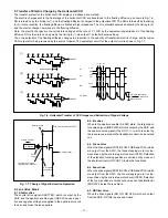
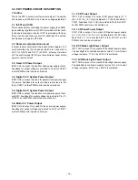
4-1. REMOVING THE PROTECTIVE SPACER AND NOTES
If the camera is dropped or subjected to other strong shocks, it may damage the mechanical pickup function. To prevent the
possibility of this happening, attach the protective spacer to the camera when transporting the camera.
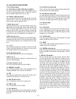
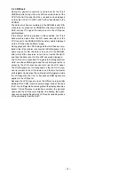
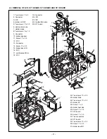
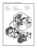
4-2. REMOVAL OF CABINET ASSEMBLY
1. Three screws 1.7 x 5
2. Screws 1.7 x 4
3. Cabinet top
4. FPC
5. Two screws 1.7 x 3.5
6. Four screws 1.7 x 3
7. Cabinet lens L
8. Cabinet VF
9. Six screws 1.7 x 4
10. Screw 1.7 x 2.5
11. Cover bottom
12. Cabinet back
13. Screw 1.7 x 3.5
14. Screw 1.7 x 2.5
15. Screw 1.7 x 5
16. Cabinet front
17. Cabinet lens R
18. Connector
19. FPC
20. Screw 1.7 x 2.5
21. SY2 board
22. Screw 1.7 x 3.5
23. Flexible PWB unit
24. Two FPCs
25. Connector
26. Cabinet jog B
27. Two screws 1.7 x 2.5
28. Button AWB
29. Five screws 1.7 x 4
30. SY4 board
31. Two screws 1.7 x 4
32. Holder zoom A
33. Push the button.
34. Three screws 1.7 x 2.5
35. Screw 1.7 x 5
36. Holder flash B
37. Two screws 1.7 x 4
38. Screw 1.7 x 6
39. Cabinet bottom
40. Open the cover
battery.
41. Screw 1.7 x 2.5
42. Screw 1.7 x 5
43. Screw 1.7 x 5
44. Connector
45. Ring MF
46. Cabinet side L
A
A
C
C
D
D
B
B
38
37
39
1
1
3
4
5
6
6
7
8
9
9
10
11
12
13
1
14
15
16
9
46
36
17
18
19
20
21
22
25
26
27
28
29
30
31
32
33
34
35
40
41
42
43
44
45
23
24
2
1. Push the eject lever in the direction
of the arrow to open the
disk holder.
2. Gently pull out the
protective spacer.

