background image

2

English

INTRODUCTION

Main features

This digital video recorder can be used to store images 
recorded by a monitoring camera onto its built-in hard disk.

„

Complete range of recording/playback 
functions

z

You can play back and record images at the same 
time.

z

You can record and play back audio.

z

The timer record function lets you make recordings 
at different times each day. (

J

P.31)

„

The search function lets you instantly display 
the desired image. (

J

P.18)

z

Searching in order of alarm occurrence

z

Searching by date/time

„

The security lock function lets you restrict 
users for data and equipment management. 
(

J

P.36)

„

Expandable, can be connected to a PC

z

The LAN terminal lets you connect the digital video 
recorder to a network, for remote operation/remote 
monitoring.*

z

Network connection lets you control up to 4,000 
DVRs (digital video recorders) using 8 PCs.*

z

Can be connected to a system controller (sold 
separately) using the RS-485 terminal.

z

A CompactFlash reader or CD-R/RW drive can be 
connected using the USB terminal, letting you 
upload/download menu data and copy recorded 
images onto a CD-R/RW.

Items marked by asterisks (*) require the VA-SW814/
VA-SW81LITE remote operation software (sold 
separately). For more information, contact a Sanyo 
service center.

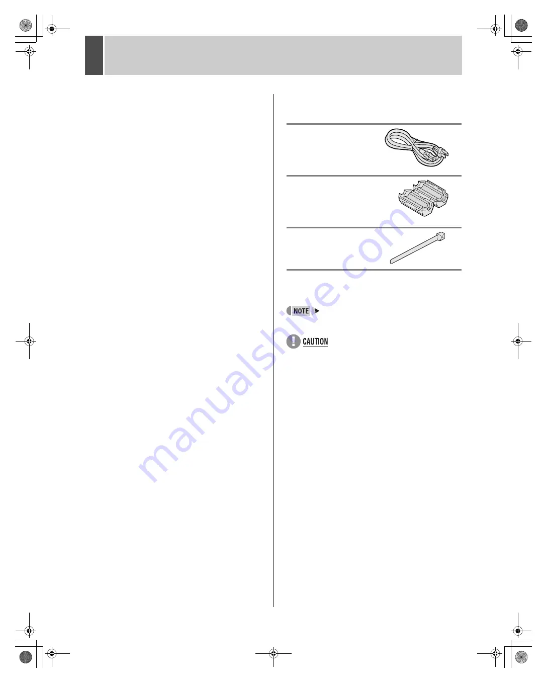
Accessories

Check that you have all the parts below.

Power cord 

Ferrite core

(for LAN connection cable)

Power cord tie 

Symbols used in this manual

Information describing operation methods 
or how to get the most out of functions

Information describing the correct use of 
the digital video recorder

(

J

P. xx)


Indicates manual page to refer to.

Copyright

z

This manual and software are copyrighted by Sanyo 
Electric Co., Ltd.

z

Brand and product names used in this manual are the 
trademarks or registered trademarks of their respective 
companies.

z

Except for personal use, copyright law prohibits the use 
of recorded copyrighted images without the permission 
of the copyright holder

z

Sanyo’s DSR-M810 Digital Video Recorder uses 
software components distributed as freeware based on 
end user license agreements or copyright notifications 
(collectively referred to as “EULA”) set forth by third 
parties.

e00_l8hae_us_7.book  Page 2  Thursday, April 8, 2004  11:14 AM

Summary of Contents for DSR-M810

Page 1: ...e00_l8hae_us_7 book Page 0 Thursday April 8 2004 11 14 AM ...

Page 2: ... Do not handle the power cord with wet hands z Do not pull on the power cord when disconnecting it from an AC wall outlet Grasp it by the plug z If any liquid is spilled on the unit unplug the power cord immediately and have the unit inspected at a factory authorised service centre z Do not place anything directly on top of this unit SERVICE This unit is a precision instruments and if treated with...

Page 3: ...sing the USB terminal letting you upload download menu data and copy recorded images onto a CD R RW Items marked by asterisks require the VA SW814 VA SW81LITE remote operation software sold separately For more information contact a Sanyo service center Accessories Check that you have all the parts below Power cord Ferrite core for LAN connection cable Power cord tie Symbols used in this manual Inf...

Page 4: ...CREEN DISPLAY AND POSITION 11 Operation display area 11 Changing the position of the operating display 11 2 SETTING THE LANGUAGE CLOCK 12 To change the language 12 Setting the time 13 3 NORMAL RECORDING TIMER RECORDING 14 Normal recording 14 Timer recording 14 4 ALARM RECORDING 15 Alarm recording 15 5 NORMAL RECORDING TIMER RECORDING PLAYBACK 16 Playback 16 Playback while fast forwarding rewinding...

Page 5: ...re than 24 hours 32 Setting holidays 33 4 DISPLAY BUZZER SET 34 DISPLAY BUZZER SET setting items 34 Settings 35 5 SECURITY LOCK SET 36 Password setting example 36 Password setting 36 Setting passwords 36 Setting the user password 37 Setting the authorization for recording and playback operations 38 Setting the security lock 38 6 RS 485 NETWORK SET 39 Network connections and settings 39 RS 485 conn...

Page 6: ...tightened securely so that they will not become loose The HDD is sensitive to static electricity so you should take proper precautions to prevent static electricity buildup Handling the HDD unit by itself If transporting or storing the HDD unit by itself always be sure to pack it in the specified packing first In addition use a method of transportation that minimizes the vibration If the HDD becom...

Page 7: ...nzene or paint thinner Doing so may break down the finish or strip the paint z When using a chemical cloth be sure to follow the precautions provided with it z Do not spray insecticide or other volatile chemicals on the cabinet Do not allow rubber or vinyl products to come into contact with the digital video recorder for extended periods z Doing so may break down the finish or strip the paint Duri...

Page 8: ...ng playback stops playback 11 ALARM indicator Flashes when recording an alarm image 12 REC STOP button and indicator Starts normal recording Indicator lights during recording During recording pressing the button for at least 3 seconds stops recording and turns off the indicator 13 FULL indicator JP 14 Lights when the remaining memory in the hard disk s recording area has reached zero and recording...

Page 9: ...n SERIES REC OUT is OFF 3 The following warnings are output z Hard disk drive error z Fan error z Recording error z No input signal when VIDEO LOSS is ON 14 ALL RESET switch Resets the clock and backup mode setting AUDIO RS485 REMOTE CLOCK NONRECOUT SERIESRECOUT ALARM RESET ALARM OUT ALARM IN WARNING OUT ALL RESET FULL OUT ADJ SERIES REC IN A B C C C IN OUT LAN VIDEO MIC IN IN OUT IN LOOP OUT OUT ...

Page 10: ... 5 or finer z In order to stop recording using the remote control REC button REMOTE SET must be set JP 41 Basic connections AUDIO AC IN ALL RESET LAN VIDEO MIC IN IN OUT IN OUT TV SYSTEM NTSC PAL AUDIO ADDRESS RS485 REMOTE CLOCK NONRECOUT SERIESRECOUT ALARM RESET ALARM OUT ALARM IN WARNING OUT ALL RESET FULL OUT ADJ SERIES REC IN A B C C C IN OUT LAN VIDEO MIC IN IN OUT IN LOOP OUT OUT TV SYSTEM R...

Page 11: ... flashes The digital video recorder has a self check function that detects problems If there is a problem at power ON or during operation the type of problem is indicated by how rapidly the POWER indicator flashes Contact a Sanyo Authorized Service Center if the POWER indicator flashes 4 flashes per second The hard disk is checked automatically at power ON If a hard disk problem is found the POWER...

Page 12: ...ng and playback points 7 Alarm display and alarm count display JP 15 When you set an alarm using the REC MODE SET menu item the alarm display area appears as shown below z Alarm display When alarm recording is set Alarm appears During alarm recording the Alarm display flashes z Alarm count display Displays the total number of alarms that have been generated 8 Name set for the digital video recorde...

Page 13: ...e cursor is positioned on ENGLISH 3 Press the button then the or button to select the desired language The set item flashes 4 When you have made a selection press the button The cursor moves to the date and time The language has now been set To return to the normal screen press the EXIT OSD button button button button MENU button Item Setting Description 1 LANGUAGE ENGLISH Sets the language to Eng...

Page 14: ...utton 01 indicating the month flashes 5 Press the or button to select 05 6 Press the button 01 indicating the day flashes 7 Use the same procedure to set the day 20 year 2004 hour 08 and minute 30 When you have set the minute the cursor moves to MODE under DAYLIGHT SAVING and the clock starts from 00 seconds z The day of the week is set automatically z The time is stopped during clock setting 8 Pr...

Page 15: ...rding symbol appears in the screen and recording starts 3 When the set end time arrives the REC indicator goes out and recording stops 4 The following restrictions apply to normal recording and timer recording z After making PICTURE QUALITY or AUDIO RECORDING menu settings and returning to the camera screen recording does not start for a maximum of 6 seconds although normal recording and timer rec...

Page 16: ...shing and recording ends z When the hard disk s remaining space for recording reaches zero the FULL indicator lights and recording ends You can start recording from the beginning again by changing the recording setting JP 29 The following restrictions apply to alarm recording 1 Just after recording starts STOP REC STOP indicator lights 2 After making PICTURE QUALITY or AUDIO RECORDING menu setting...

Page 17: ...utton appears in the operation display and the playback fast forwards at 7 5 times the normal playback speed When you press the button appears in the operation display and the playback fast rewinds at 7 5 times the normal playback speed Press the button while fast forwarding Press the button once to increase the speed to 15 times the playback speed twice to increase the speed to 30 times the playb...

Page 18: ...ches the playback speed to 1 4 the normal speed Pressing the button twice switches the playback speed to 1 2 the normal speed Press the button for at least 2 seconds The playback speed slows to 1 8 the normal speed Pressing the button again switches the playback speed to 1 4 the normal speed Pressing the button twice switches the playback speed to 1 2 the normal speed Viewing still images To resum...

Page 19: ... Lets you search and play back recorded alarm images 1 Press the SEARCH button while the digital video recorder is recording or stopped The SEARCH COPY screen appears 2 Check that ALARM SEARCH is selected and press the button The ALARM SEARCH screen appears The 8 latest alarm images are listed on the screen 1 NO Displays the alarm number 2 DATE TIME Displays the date time at which the alarm was re...

Page 20: ...umber Press the button to move the cursor 3 Press the button The image corresponding to the entered alarm number appears Follow the steps below to search an image recorded by specifying its recorded date and time 1 Press the SEARCH button while the digital video recorder is recording or stopped The SEARCH COPY screen appears 2 Press the or button to select TIME DATE SEARCH 3 Press the button The T...

Page 21: ...to the preview 5 Press the button z If no image exists for the specified time The image for the time closest to the selected time is displayed z To end search mode Press the EXIT OSD button 6 Press the button to select VIEW then press the button The image in the preview screen is played back on the entire screen z You can enter the desired date and time and select VIEW to display the retrieved ima...

Page 22: ...EARCH button while the digital video recorder is recording or stopped The SEARCH COPY screen appears 2 Press the and buttons to select COPY SET and press the button The COPY SET screen appears 1 RECORDING TOP Displays the date time of the image recorded first 2 RECORDING END Displays the date time of the image recorded last i e the newest image 3 COPY SIZE Displays the amount of data between START...

Page 23: ...0 will be used when creating folders z The character will be used to replace any backslash semi colon asterisk period or colon characters appearing in DVR NAME z When adding data to the same CompactFlash card folders such as Folder name 1 will be created 1 Press the SEARCH button while the digital video recorder is recording or stopped The SEARCH COPY screen appears 2 Press the and buttons to sele...

Page 24: ...released at power OFF z You cannot set the key lock during playback 1 Press the button for about 3 seconds while the key lock function is set When the key lock is released a confirmation tone sounds and the LOCK REMOTE indicator goes out z When the key lock function has been set the buttons can t be used for settings or operations z When the security lock is set you cannot set the key lock alone z...

Page 25: ...ettings In the sub menu screen use the buttons to enter the desired setting 1 To move the cursor up down Press the or button 2 To move the cursor right or to a setting item Press the or button 3 To change a setting value Press the or button Follow the steps below to restore just the currently displayed menu items to their initial values 1 Display the desired sub menu screen 2 Press the MENU RESET ...

Page 26: ...the buzzer on the following occasions z During alarms z When there is no more available recording space z When the operation button is pressed z When there is a hard disk problem z When there is a fan problem z When there is a recording problem z When there is VIDEO LOSS 5 SECURITY LOCK SET JP 36 Lets you set passwords to restrict the users 6 RS 485 NETWORK REMOTE SET JP 39 Used to make the settin...

Page 27: ... button The LANGUAGE LANGUE IDIOMA screen appears with the cursor positioned on ENGLISH 3 Press the or button to select MODE under DAYLIGHT SAVING 4 Press the button USE flashes 5 Press the or button to change the setting Settings indicates initial setting 6 Press the button The cursor moves to the date time at which to switch from standard time to daylight savings time DAYLIGHT SAVING settings MA...

Page 28: ...onth then press the button The cursor moves to TIME 11Press the and buttons to select the desired time then press the button The cursor moves to the minutes portion of the time Set the desired minutes in the same manner 12Press the EXIT OSD button The display returns to the normal screen This section describes how to have the time synchronized automatically when two or more digital video recorders...

Page 29: ...n 6 Use the same procedure to set the time on the second digital video recorder When you have finished making the settings the display returns to the normal screen z When the digital video recorder is connected to a PC or other external device through a network you can also set the time from that device When connected to a PC see the instructions for the VA SW814 VA SW81LITE application software T...

Page 30: ...d over previously recorded images once The WARNING screen appears Press the or button to select YES 6 SERIES REC OFF Series recording is not performed 1M When multiple digital video recorders are connected about 1 minute before the first recorder s hard disk becomes full the second recorder s hard disk starts recording 2M When multiple digital video recorders are connected about 2 minutes before t...

Page 31: ...LL indicator lights and recording stops To start recording again first follow the steps below to erase the images recorded so far 1 Display the REC MODE SET screen 2 Press the or button to select DISK FULL RESET then press the button The DISK FULL RESET screen appears with NO flashing 3 Press the or button to select YES then press the button The images recorded so far are erased and the display re...

Page 32: ...mer recording setting Setting OFF disables the entered timer recording setting 5 Used for timer recording settings of over 24 hours Use these lines for timer recording of over 24 hours 6 HOLIDAY SET JP 33 Example Timer recording every day from 8 30 AM to 6 30 PM with the same recording rate 1 Press the MENU button The MENU indicator lights and the MAIN MENU screen appears 2 Select 3 TIMER REC SET ...

Page 33: ...ve priority 1 Press the MENU RESET button while the TIMER REC SET screen is displayed All the timer settings are erased This section describes how to use timer reservations to record for more than 24 hours These settings are made using lines 7 initially SAT and 8 initially DLY of the TIMER REC SET screen Example Timer recording from 10 30 AM Monday to 8 30 PM Wednesday 1 Press the or button to mov...

Page 34: ...on for Sunday used on those days Dates such as national holidays and company off days should be set as holidays when you want those dates to have the same security as Sundays Setting conditions Be sure to set holidays after first making timer settings for Sunday JP 31 Example To set November 17 as a holiday z You can set up to 20 days as holidays 1 Press the or button to select HOLIDAY SET then pr...

Page 35: ...e set for digital video recorder 4 ALARM COUNT ON Display current alarm count in operation display area OFF Don t display current alarm count in operation display area 5 ALARM ON ON Sound buzzer when alarm is received OFF Don t sound buzzer when alarm is received 6 DISK FULL ON When OVER WRITE is not set sound buzzer when remaining hard disk space reaches zero OFF When OVER WRITE is not set don t ...

Page 36: ...en appears 3 Press the and buttons to select the desired item then press the button 4 Press the and buttons to change the setting then press the button 5 Use the same procedure to set the other items as needed 6 Press the EXIT OSD button The display returns to the normal screen Settings button MENU button button button EXIT OSD button e00_l8hae_us_7 book Page 35 Thursday April 8 2004 11 14 AM ...

Page 37: ... Administrator enters password All operations can be performed ADMIN 123456AB ON USER AB123456 ON REC CONTROL USER No password is entered All operations are locked User enters password Only playback and recording operations can be performed Administrator enters password All operations can be performed ADMIN 123456AB ON USER OFF REC CONTROL ADMIN No password is entered Only playback operations can ...

Page 38: ...ting press the button The cursor moves to USER If you don t want to set a user password the password setting is now finished Press the button to move the cursor to REC CONTROL to set the authorization for recording and playback operation JP 38 Example Setting AB123456 1 Press the and buttons to move the cursor to USER 2 Press the button The first password entry bar flashes Example A Press the and ...

Page 39: ...o check the security lock press any button The password entry screen appears for about 5 seconds 3 Enter the password while the password entry screen is displayed Enter the password using the and buttons z Enter the password set for administrators or users such as 123456AB 4 Press the button The setting is now finished The LOCK REMOTE indicator goes out and the display returns to the normal screen...

Page 40: ... MAIN MENU screen appears 2 Select 6 RS 485 NET WORK REMOTE SET and press the button The RS 485 NETWORK REMOTE SET screen appears Settings indicates default setting Network connections and settings AUDIO ALL RESET LAN VIDEO MIC IN IN OUT IN OUT TV SYSTEM NTSC PAL A IN 10 IN AUDIO ALL RESET LAN VIDEO MIC IN IN OUT IN OUT TV SYSTEM NTSC PAL A IN 10 IN AUDIO ALL RESET LAN VIDEO MIC IN IN OUT IN OUT T...

Page 41: ... will become valid upon leaving the RS 485 NETWORK REMOTE SET screen z When connecting the digital video recorder to a network check the IP address with the network administrator The set IP address is displayed in the RS 485 NETWORK REMOTE SET screen Connect the digital video recorder s RS 485 A B control terminals in series to the system controller digital video recorder or similar device 1 Press...

Page 42: ...reen appears 2 Press the and buttons to select REC STOP and press the button DISABLE flashes 3 Press the and buttons to change the setting then press the button Settings indicates initial setting 4 Press the EXIT OSD button The display returns to the normal screen Item Setting Description 1 REMOTE AS VCR When the digital video recorder is operated from a controller sets it to operate as a VCR DVR ...

Page 43: ...R Displays the date and time of occurrence and restoration for the four most recent power failures The number on the left is the number of power failures example 002 Resets to 000 after exceeding 999 2 DISK1 USE Displays the total amount of disk 1 operation time 3 DISK2 USE Displays the total amount of disk 2 operation time when second disk has been added 4 POWER Displays the amount of power ON ti...

Page 44: ...en the menu cannot be saved to the CompactFlash card consecutively remove the CompactFlash card reinsert and try again z At least 2 KB of available memory space is needed on the CompactFlash card z The file name is M810MENU txt You will need a CompactFlash card reader and CompactFlash card commercially available 1 Press the MENU button The MENU indicator lights and the MAIN MENU screen appears 2 S...

Page 45: ...s the and buttons to select YES then press the button Uploading starts When you have finished loading the display returns to the MENU UPLOAD DOWNLOAD screen If MIRRORING setting is loaded z If COPY MIRRORING SETTINGS is set to YES the hard disk may be initialized If you don t want to initialize the hard disk select NO 1 Press the and buttons to select COPY MIRRORING SETTINGS and press the button N...

Page 46: ...uttons to select FORMAT CF then press the button The WARNING screen appears NO flashes 2 Press the and buttons to select YES then press the button CompactFlash card formatting starts When you have finished formatting the display returns to the MENU UPLOAD DOWNLOAD screen z Formatting a CompactFlash card erases all the data stored on it To cancel formatting select NO 1 Press the EXIT OSD button The...

Page 47: ...ALIZE 3 Press the button The WARNING screen appears NO flashes 4 Press the and buttons to select YES then press the button The HDD INITIALIZING screen appears and the hard disk is initialized reformatted When the process has finished the display returns to the MENU screen 5 Press the EXIT OSD button The display returns to the normal screen MAIN MENU button MENU button button button EXIT OSD button...

Page 48: ...ny data on the original hard disk will be erased Hard disk setting screen z Mirroring After adding a hard disk you can record the same image on both hard disks If an image write error occurs on one disk you can still read the image from the other z Playback disk When mirroring is set the digital video recorder automatically sets which of the two hard disks to read the recorded image from Adding a ...

Page 49: ... set the RS 485 termination switches of all devices in between devices other than the first and last devices to OFF z If you don t make the correct termination settings the incorrect data will be transmitted to each device Example RS 485 specifications Mode Asynchronous Character length 8 bits Data transmission speed 2400 4800 9600 19200 bps Parity check None Stop bit 1 bit RS 485 termination swit...

Page 50: ... SHIFT RP DOWN 7 8 9 SECURITY LOCK ON A ACK PLAY REV PLAY SEARCH DVR SECURITY LOCK OFF B NAK C GROUP SET D GROUP CHECK E GROUP CLEAR F STOP STILL Left digit Right digit 8 9 A B C D E F 0 CLOCK ADJUST 1 MENU RESET 2 3 4 5 6 T L STATUS SENSE 7 STATUS SENSE 8 9 CLOCK DOWNLOAD A REC REC DUB REQUEST B FF C REW D RS 485 SEND START E OSD EXIT STATUS LOG2 RS 485 RCV CMF F STATUS LOG1 REC STOP e00_l8hae_us...

Page 51: ...ced RCA pin jack Microphone input terminal 60 dBs 10 kΩ unbalanced 3 5 mm mini jack LAN terminal 100BASE TX 10BASE T RJ 45 USB terminal For CompactFlash reader and CD R RW drive Front Control connector Push lock RS 485 terminal 3 terminals A B GND Remote control input terminal External switch connection or VA RMN01 remote control Clock adjust input terminal Normal open Low level active Clock adjus...

Page 52: ...2 SPECIFICATIONS English 51 Unit mm Dimensions Front Side 210 380 96 e00_l8hae_us_7 book Page 51 Thursday April 8 2004 11 14 AM ...

Page 53: ...ash cards 43 initialize the hard disk 46 K KEY IN 34 key lock 23 L LANGUAGE 12 LANGUAGE CLOCK SET 12 LOCK REMOTE indicator 38 M MAIN MENU 25 MENU button 24 MENU RESET button 24 MENU UPLOAD DOWNLOAD 43 Mirroring 47 N NETWORK SET 39 NON REC 34 Normal recording 14 O OVER WRITE 29 P Password 36 PICTURE QUALITY 29 PLAY STOP button 16 Playback 16 Playback disk 47 Playback while fast forwarding rewinding...

Page 54: ...ton 14 TIMER indicator 14 TIMER REC SET 31 Timer recording 14 Timer reservations spanning more than 24 hours 32 TV SYSTEM selector switch 8 U UP button 16 USED TIME 42 USER 36 V VIDEO LOSS 29 W WARNING 34 e00_l8hae_us_7 book Page 53 Thursday April 8 2004 11 14 AM ...

Page 55: ...sp00_l8hae_us_7 book Page 55 Thursday April 8 2004 11 43 AM ...

Reviews: