— 12 —
MAGNET TABS
ANGLE OF MAGNET TABS
SIX-POLE
MAGNET TABS
FOUR-POLE
MAGNET TABS
ANGLE
OF TABS
PURITY
MAGNET
TABS
4
3
2
1
FOCUS GAP
(G3-G4)
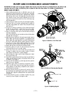
Figure 3. Adjusting Magnet
Figure 2. Purity and Convergence Magnets
PURITY ADJUSTMENTS
1. When replacing picture tube or deflection yoke, mount
deflection yoke and purity and convergence magnets
assembly properly. See Figure 1. Position the picture
tube facing east or west. Demagnetize the picture tube
and receiver using an external degaussing coil. Set
receiver to Service Menu NO. A9 (no vertical sweep)
while degaussing.
2. Place the yoke on tube neck fully forward against glass.
3. Place the CPM on the tube neck aligning the center of
the purity magnet tabs over center of Focus Gap (G3 & G4).
See Figure 2.
4. Connect a color-bar generator to the antenna terminal.
Switch the generator to a white field. Move yoke back-
ward on the neck until a uniform white field is obtained.
5. Allow 30 minutes warm up on a blank white field (high
intensity grayscale).
Note: If white field cannot be obtained check Grayscale
Adjustments on page 9.
6. Reset the picture controls to the Auto levels. Select a green
raster, either with the signal generator or by adjusting the
bias controls. If a signal generator is used for this step skip
to Step 11. If the bias controls will be used go to step 7.
7. Adjust Service Menu NO. 49 RB (Red Bias), NO. 4A GB
(Green Bias), and NO. 4B BB (Blue Bias) data each to 00.
8. Select Service Menu NO. A9 (no vertical sweep).
9. Adjust the Screen Control counterclockwise until the
horizontal scan line is no longer visible.
10. Select Service Menu NO. 4A GB (Green Bias) and
increase the data to produce a green raster. If retrace
lines appear reduce screen control slightly.
11. Pull yoke back on tube neck to obtain three-color raster
(blue, green and red).
12. Adjust the angle between the two purity magnet tabs to
center the vertical green belt in the picture tube. Do not
rotate tabs. See Figure 3.
13. Slowly slide the deflection yoke forward until a uniform
green screen is obtained.
14. Check the purity of the red and blue screens for unifor-
mity. Turn off other colors to check (use bias controls or
use generator). If necessary, readjust the yoke position
until all screens are pure.
15. If bias controls and screen control were used to set puri-
ty reset Grayscale and Bright Level. Refer to Grayscale
Adjustment on page 9 and Brightness Level Adjustment
on page 9.
16. Confirm that the yoke is not tilted. Tighten the yoke
mounting screw. Adjust convergence next.
RUBBER
WEDGE
DEFLECTION YOKE
DEFLECTION YOKE
MOUNTING SCREW
Figure 1. Deflection Yoke Movement
PURITY AND CONVERGENCE ADJUSTMENTS
CAUTION: The Purity and Convergence adjustments have been made at the factory. Readjustments should be made
only after the picture tube or deflection yoke is replaced. Follow the steps below for necessary readjustments.


