


– 6 –
MECHANICAL DISASSEMBLY
CAUTION: This LCD TV uses several different kinds of screws. Using the correct screw is necessary to
prevent damage. Lead wires must be redressed to their previous locations after servicing.
B
B
STAND REMOVAL
Position TV face down on a padded or cushioned surface
to protect the screen and finish.
Remove 4 screws (B: 6X16) to take the stand off.
BACK CABINET REMOVAL
1. Remove the screws shown in figure.
(C:3x14, 12 pcs.; D4x8, 4 pcs.; A3x6, 1 pcs.)
2. Lift the back cabinet and remove the lead wire connector.
3. Take the back cabinet off.
C
C
C
C
C
C
C
C
C
C
C
C
D
D
D
D
A
Main Board
Power Unit
C
C
C
C
C
C
C
C
C
C
C
C
C
C
[ATTENTION]
Please do not tighten the
(D)
screw too strongly when you
install the back cabinet againg. The screw comes not to be
tightened.
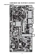
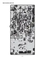
MAIN BOARD REMOVAL
Remove 7 screws (C:3x6) to take the main board off.
POWER UNIT REMOVAL
Remove 7 screws (C:3x6) to take the power unit off.
Summary of Contents for DP32649 - 32" LCD TV
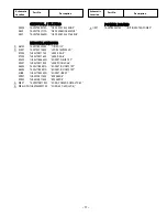
Page 23: ... 23 IC BLOCK DIAGRAMS IC001 Audio AMP ...
Page 24: ... 24 IC1670 Voltage Regulator IC803 EEPROM IC BLOCK DIAGRAMS CONT ...
Page 25: ... 25 IC1680 DC to DC Regulator IC1600 DC to DC Converter ...
Page 26: ... 26 IC5500 Video Processing IC BLOCK DIAGRAMS CONT ...
Page 27: ... 27 IC6600 USB protection IC6270 Low output Amplifier ...
Page 28: ... 28 IC5700 DDR Double Data Rate SDRAM IC BLOCK DIAGRAMS CONT ...


