


18
3. Troubleshooting guide
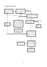
3.1. No raster
Turn-on power supply, check
if the red indicator is light in
the STANDBY?
Check if X303 PIN3(5V) of
main board is normal?
Check STANDBY circuit of
power supply board
Press POWER button on the
unit or remote sensor control
and check the indicator.
Check if the PIN3 of X301 on
main board is high-level?
Check if the PIN11 of X303 in
main board is high-level?
Check power
supply board
Check back light board
yes
no
no
red
blue
no
yes
Replace NS4
no
yes
Replace N102
Summary of Contents for AVL-3210
Page 12: ...10 ...
Page 14: ...12 ...
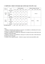
Page 15: ...13 Pin description 1 7 L R input 19 14 L R output 6 10 mute control input ...
Page 16: ...down up down up down up IF adjustment Wiring diagram 14 ...
Page 23: ......
Page 24: ......
Page 25: ......
Page 26: ......
Page 27: ......
Page 28: ......
Page 29: ......
Page 30: ......
Page 31: ......
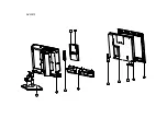
Page 33: ...1 2 3 4 5 6 7 8 9 11 10 AVL3210 ...
Page 36: ...Mar 2008 ...


