-15-
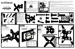
Special Function
TUNING LOCK
AV START
VOLUME LOCK
MUSIC MODE
OFF
OFF
OFF
OFF
SELECT ADJUST
M
EXIT
1
To enter into the special function setting mode, press and
hold the
MENU
button of the remote control, then press the
PROGRAMME DOWN
button on the TV set.
Once TUNING LOCK is switched on, further channel tuning
(Pre-set) is not possible. The Channel Swapping function also
is not possible.
2
Select an item of the special functions by pressing the
PROGRAMME UP
or
DOWN
button on the remote control
or the TV set.
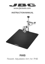
3
Set the selected special function “ ON “ by pressing the
or
-
button. To cancel, set to “ OFF”.
(2) Tuning Lock setting
The following special functions can be set up on this TV
set.
With this function, a maximum sound volume limit can be set at
any level.
(3) Music Mode setting
When Music Mode is ON, Programme position from “91” to “99”
and “0” are set Music Mode. Only sound is provided and any
picture is not on the screen under Music Mode.
Set AV-START to ON and every time the TV set is switched on,
AV position will be the initial programme position.
(4) AV Start setting
TUNING LOCKED
How to set the special function:
Note:
When making the VOLUME LOCK setting, set the
desired maximum sound volume by pressing the
or
-
button before entering Special Function setting mode.
AV
MUSIC
Turns black
screen
4
Press the
MENU
button of the remote control to return to
the normal TV mode.
(1) Volume Lock setting
P
▲
P
▼
P
▲
P
▼
SOUND
BASS EXPANDER ON
IIIIIIII
MENU
MENU
OFF
ON
OFF
OFF
TUNING LOCK
AV START
VOLUME LOCK
MUSIC MODE
SELECT ADJUST
M
EXIT
OFF
OFF
OFF
OFF
TUNING LOCK
AV START
VOLUME LOCK
MUSIC MODE
SELECT ADJUST
M
EXIT
CH
Summary of Contents for 111359614
Page 26: ... 26 ...
Page 27: ... 27 ...
Page 28: ...SANYO Electric Co Ltd A14800 Nov 03 30 BB Printed in Japan ...