Appendix: Installing the Stand
To install the stand:
Cautions:
Make sure that you handle your TV very carefully when attempting assembly or removal of the stand. If you are not
sure of your ability to do this, or of your ability to use the tools necessary to complete this job, refer to a professional
installer or service personnel. The manufacturer is not responsible for any damages or injuries that occur due to
mishandling or improper assembly.
The speaker is not intended to support the weight of your TV. Do not move or handle your TV by the speaker. This
can cause damage to your TV that is not covered by the manufacturer's warranty.
Before attempting assembly or removal of the stand, unplug the AC power cord.
You must install your TV into the stand in order for it to stand upright on a cabinet or other flat surface. If you intend
to mount your TV on a wall or other vertical surface, you must remove the stand column.
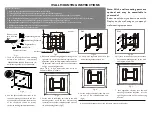
1.
Carefully place your TV screen face-down on a cushioned, clean
surface to protect the screen from damages and scratches.
2.
Secure the stand to the TV with the three provided screws.
If the stand is provided, please read these instructions thoroughly before attempting this installation.
NOTE:
The appearance of this product in
these illustrations may differ from
your actual product, and is for
comparative purposes only.
Adjusting the viewing angle
Backward
To adjust the viewing angle:
!
Tilt the screen forward or backward.
Caution:
When adjusting the viewing angle, be careful not to tip over
your TV.
Installing a wall-mount bracket
(not provided)
Installing the stand
Note: If you are mounting the TV and plan on using the
back inputs, a low profile wall mount may not work with
your TV.
To attach your TV to a wall-mount bracket (not provided)
1.
Carefully place your TV screen face-down on a cushioned, clean
surface to protect the screen from damages and scratches.
2.
Remove the two screws holding the TV to its stand column.
3.
Remove the stand column.
4.
Secure the wall-mount bracket to the back of your TV using the four
screws provided with the bracket.
Forward
Summary of Contents for 1 682 351 01
Page 17: ...Speakers Block Diagram N204 NB08 BH3547F NV01 1 ...
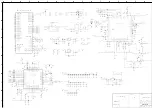
Page 30: ...Power board ...
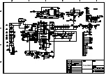
Page 31: ...Backlight board ...
Page 33: ...APPENDIX B Explodedview LED 22XR11F ...
Page 38: ...June 2011 ...

