background image


- 23 - 

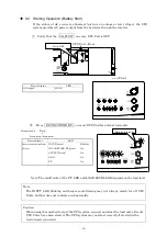
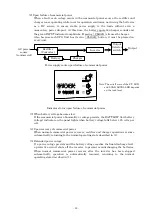
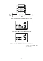
(2) Upon failure of commercial power 

When a fault or an outage occurs in the commercial power source, the rectifier and 
charger cease operating while inverter operation continues, now using the batteries 
as a DC source, to ensure stable power supply to the loads without even a 
momentary power dropout. At this time, the battery operation beeper sounds and 
the green INPUT indicator lamp blinks. Pressing    CLEAR    silences the beeper. 
Also, because each UPS Unit has its own    CLEAR    button, it must be pressed on 
every unit. 


Power supply route upon failure of commercial power 


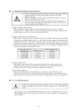
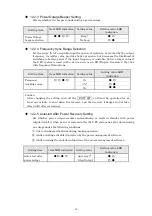
Indicator status upon failure of commercial power 


  (3) When battery voltage becomes low 

If the commercial power abnormality or outage persists, the BATT.LOW (low battery 
voltage) indicator on the panel lights when battery voltage falls below 1.85 volts per 
cell. 

 
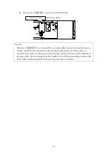
  (4) Upon recovery of commercial power 

When normal commercial power recovers, rectifier and charger operations resume 
automatically, returning to the normal operating state described in (1). 

 
  (5) Extended power outage 

If a power outage persists and the battery voltage reaches the final discharge level, 
a protective circuit shuts off the inverter to prevent overdischarging the batteries. 
When normal commercial power recovers after the inverter has been stopped 
automatically, operation is automatically resumed, returning to the normal 
operating state described in (1). 

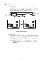
Rectifier 

(Converter)  

Inverter 

Battery 

Charger 

AC power 

source 

(commercial) 

Output 

Output 

Selector 

switch


Note: The on/off state of the F.T. LED 

and LOAD LEVEL LED depends 
on the load level. 

Summary of Contents for ASE10S1HU001

Page 1: ...M0006244B SANUPS ASE H ASE10S1HU001 ASE10S1HU001 10 ASE10S1HU001 15 ASE10S1HU001 20 Uninterruptible Power Supply Unit PDASEU01 UPS Power Distribution Unit 100V Type Instruction Manual ...

Page 2: ...of contents 1 Safety Precautions 1 2 Considerations for Proper Operation 5 2 1 Input Power Considerations 5 2 2 Installation Considerations 5 2 3 Usage Considerations 5 2 4 In Case of Trouble with the UPS 6 3 Confirming Package Contents 6 4 Overview 7 5 External Dimensions and Parts Names 9 5 1 UPS Unit 9 5 2 Control Panel Indicators 10 5 3 UPS Power Distribution Unit 11 6 Carrying and Installatio...

Page 3: ...gs 30 12 2 1 PC Interface Selection 32 12 2 2 Communications Baud Rate Selection 32 12 2 3 Power Outage Beeper Setting 33 12 2 4 Frequency Sync Range Selection 33 12 2 5 Autostart After Power Recovery Setting 33 12 2 6 INV ON STAND BY Button Response Time Setting 34 12 2 7 Ring Signal Start Setting 34 12 2 8 Battery Starting Frequency Setting 34 13 Specifications 35 14 Warranty Conditions 36 Appen...

Page 4: ...ause severe bodily injury or death as a result incorrect operation Denotes hazards which COULD cause bodily injury and product or property damage as a result incorrect operation Additionally even those hazards denoted by CAUTION could lead to a serious accident so the instructions should be strictly followed The following labels indicate particularly important instructions which must be carefully ...

Page 5: ...ust be ventilated Unless the specified ventilation airflow 5 m3 h is maintained gas produced by battery charging could result in rupture or explosion of the case Install the UPS on a stable surface capable of bearing the weight of the UPS in the correct manner specified in this manual If the UPS is installed incorrectly impact or vibration could cause it to fall or move inadvertently resulting in ...

Page 6: ...an emergency generator must be incorporated when operating maintaining and controlling systems in which a UPS is used with loads affecting life support or public infrastructure dependent applications Do not smoke or use an open flame near the UPS as it could cause the UPS to explode or rupture resulting in injury or fire Do not place containers of liquid such as a flower vase on the UPS If the con...

Page 7: ...y fluid contacting your skin or clothing Diluted sulfuric acid may cause blindness if it gets into the eye may burn skin upon contact It is electrically conductive and corrosive Observe the following procedures if electrolyte spills a Wear full eye protection and protective clothing b If sulfuric acid contacts the skin wash it off immediately with water c If sulfuric acid contacts the eyes flush t...

Page 8: ...ng the output load side If one side must be grounded the V terminal phase should always be the grounded phase to avoid short circuiting power to ground 2 3 Usage Considerations 1 Never short circuit the output terminals or connect a load which draws short circuit current Doing so causes protective functions or fuse opening to prevent output 2 Unsuitable load devices Do not connect laser printers p...

Page 9: ...f UPS Unit depends on the unit number of parallel connection The contents of each package are as follows 1 Package contents of UPS Power Distribution Unit PDASE per set a UPS Power Distribution Unit 1 unit b Accessories Instllation and Maintenance Manual 1 copy Instruction Manual this booklet 1 copy Setting Manual 1 copy PC Interface cable 1 pcs Input Output cable 5 pcs Terminal cover A 1 pcs Term...

Page 10: ...The UPS Unit consists of rectifier charger inverter battery and utility power transfer bypass circuits In the event of failure of the AC source utility power inverter operation is sustained by converted DC power supplied from the batteries When the utility power recovers inverter operation continues while the battery is recharged The UPS system is therefore able to supply completely uninterruptibl...

Page 11: ... Filter AC Output UPS Unit No 1 Control Circuit Fuse Input Fuse Bypass circuit Inverter REMOTE PC I F CARD I F Battery Rectifier Filter DC DC Converte r LAN I F optional Contact Signal optional Bypass Fuse Output Selector Switch Filter UPS Unit No 2 UPS Unit No 3 UPS Unit No 4 UPS Unit No 5 max Charger ...

Page 12: ...ard Interface CARD I F For connecting external communications and card options PC Interface PC I F For PC or workstation communications Cooling Fan Cooling Optional Card Slot OPTION CARD Compartment for installing optional card Unit Switch UNIT SW Input power on off for UPS Unit Remote On Off Connector REMOTE Connection terminal for remote On Off switch Bypass Fuse BYPASS FUSE Bypass circuit prote...

Page 13: ... minimum operating voltage Input Indicator INPUT Lights green when input utility power is normal and blinks when input power is abnormal Output Indicator OUTPUT Lights green when output power is supplied through the inverter and blinks when supplied through the bypass circuit Load Level Indicator LOAD LEVEL Indicates the load level 20 40 60 100 or O L Overload Battery Low Indicator BATT LOW Lights...

Page 14: ...mm 16 14 in Weight 9 kg 19 84 lbs No Name Marking Function Front Panel Cable Cover Terminal Brock Cover Maintenance Bypass Switch Optional MAINTENANCE BYPASS SW Molded case cam switch for maintenance normally OFF 86mm 3 39in 410mm 16 14in Optional ...

Page 15: ...re it may be subject to vibration and shock Where dust may accumulate 6 2 Carrying Carry the UPS within its packing cartons removing only when near the installation location No of Parallel Connected UPS Units Equipment type name 2 Units 3 Units 4 Units 5 Units Angle of inclination degree 30 40 50 55 6 3 Installation The UPS is designed to be installed either horizontally in a rack or vertically on...

Page 16: ... from a computer such as a PC or workstation using the optional SanGuard power control software Use the communications cable supplied with the UPS Power Distribution Unit PC I F Setting W S Mode 12 2 1 Signals are supported by the UPS monitoring functions of network operating systems such as Netware and Windows NT By connecting a computer PC or workstation with the communications cable supplied wi...

Page 17: ... Shutdown Precautions for using Remote ON One Touch Shutdown In this case an optional switch must be connected to the Remote ON OFF connector of the unit that connects to the PC If the Remote ON OFF switch is connected to a unit that is not connected to the PC One Touch Shutdown is not available Note 1 The Stand Alone and Workstation Modes are selected fron the front panel See 12 2 1 PC Interface ...

Page 18: ...fore starting operation Visually inspect the units to verify that there is no visible damage Connect the UPS to a utility power source that meets the input specifications Verify that the UNIT SW on all UPS Units is turned OFF UPS Unit Rear ON OFF UNIT SW Verify OFF ...

Page 19: ...nt In this manual switches are depicted as e g INV ON STAND BY The status of LEDs on the control panel are indicated as for lit and for blinking AT THIS TIME If the LEDs do not light as above the alarm sounds after a few seconds indicating that settings or connections may have been made incorrectly In that case please contact your nearest sales representative UNIT SW ON OFF Press the ON side Devic...

Page 20: ...INV ON STAND BY switches of more than one UPS Unit at the same time Otherwise problems such as abnormal startup may occur Hold at least 1 second Beeper Sound beep Device Status LED Cooling fan rotation rectifier and charger starting battery charge starting INPUT green On P R O green On After a second or two the inverter starts INPUT green On INV ON STAND BY green On OUTPUT green On P R O green On ...

Page 21: ...e load level Note The INPUT LED blinking and beeper sound timing may not always match for all UPS Units but this does not indicate an abnormality Caution When using this method to start the UPS system connect and start the load only after all UPS Units have been started The UPS system may not start correctly if started with a load already connected ON OFF UNIT SW Verify OFF Hold for 6 seconds Devi...

Page 22: ...mal the UPS cannot switch from the internal supply back to the utility power so operation is the same as during an extended outage and the batteries will be discharged Be aware that when restarting from this condition the UPS system backup function will not be fully operational until the batteries have had time to recharge UNIT SW ON OFF Press the ON side ...

Page 23: ...source Note The INPUT LED blinking and beeper sound timing may not always match for all UPS Units but this does not indicate an abnormality Turn the distribution panel breaker back ON Beeper sound Beep beep beep beep Device Status LED Inverter operating from battery Output supply continues INPUT green Blinking INV ON STAND BY green On OUTPUT green On P R O green On F T green On Beeper sound stops ...

Page 24: ...d the same as during an extended outage Be aware that when the input supply is restored the full capacity of the backup function will not be available until the batteries have had time to recharge ON OFF UNIT SW Hold at least 1 second Press the OFF side Device Status LED Inverter stopped OUTPUT stopped Rectifier charger operation continue INPUT green On INV ON STAND BY green Off OUTPUT green Off P...

Page 25: ... AC power is synchronized with the commercial source to ensure a stable power supply to the loads The batteries are kept continually charged and ready in case a problem outage or voltage drop occurs in the commercial power supply Power supply route in normal operation Indicator status All UPS Units Note The on off state of the F T LED and LOAD LEVEL LED depends on the load level AC power source co...

Page 26: ...mality or outage persists the BATT LOW low battery voltage indicator on the panel lights when battery voltage falls below 1 85 volts per cell 4 Upon recovery of commercial power When normal commercial power recovers rectifier and charger operations resume automatically returning to the normal operating state described in 1 5 Extended power outage If a power outage persists and the battery voltage ...

Page 27: ...s during overload 2 Inverter Failure If a fault occurs in an inverter the faulty unit is automatically isolated as inverter supply continues from the normal unit s The red ALARM indicator on the faulty unit lights and its beeper sounds Press CLEAR to silence the beeper At that time operation is as follows depending on the size of the load current Case 1 If the load current does not exceed the capa...

Page 28: ...atus when a UPS Unit has failed faulty Unit Indicator status when a UPS Unit has failed normal Units Case 1 For Case 2 operation is the same as the overload state AC Input Unit No 1 Unit No 2 Unit No 3 Unit No 4 AC Output Power Dist Maintenance Bypass SW Optional Unit No 5 ...

Page 29: ...5 Input overvoltage blink 1 2 Rectifier and charger turned off Inverter power supply is continued Battery operation 06 Input overvoltage prolonged blink 1 3 Rectifier and charger turned off Inverter power supply is continued Battery operation Inverter turns off when battery discharged 07 Power outage blink 1 2 Rectifier and charger turned off Inverter power supply is continued Battery operation 08...

Page 30: ...herwise result Perform inspection only after the input power has been turned off and the UPS has completely stopped Electric shock hazards may be present As electrical parts remain charged as long as the batteries are connected never touch them Electric shock hazards may be present 1 External Visual Inspection Damage can occur if dust accumulates on internal components so remove any dust or grime ...

Page 31: ...re Using batteries after their life expectancy can cause leakage and in the worst case damage may result so we recommend changing batteries early as a preventative and protective step Ambient Operating Temperature Life Expectancy Battery Replacement Period 25 C 77 F 5 0 years 4 5 years 30 C 86 F 3 5 years 3 0 years 35 C 95 F 2 5 years 2 0 years 40 C 104 F 1 7 years 1 5 years 3 Battery Specificatio...

Page 32: ...nit is found testing of the other UPS Unit s is aborted Battery Test Results Indication Backup confirmation time Judgment Lit more than 2 min Batteries are normal Long blinking less than 2 min Replace batteries soon Off Battery test aborted If necessary press BATT TEST to abort the battery test Normal operation resumes When finished the test and after verifying battery test results press CLEAR on ...

Page 33: ...t panel settings affect only the UPS Unit on which they are made the other UPS Units are not affected However the same settings should be made on all UPS Units During inverter or standby operation press CLEAR for at least 3 seconds The blinking pattern of the upper four LEDs now indicates the item to be set 13 2 1 to 13 2 8 selected by pressing CLEAR briefly less than 3 seconds The blinking positi...

Page 34: ...ss BATT TEST so press it as necessary to select the desired setting value Press CLEAR for at least 3 seconds when finished making settings Two beeps sound the setting status is memorized and normal operation resumes Note To reset all settings to their defaults initial settings press and hold CLEAR for more than 3 seconds after the beeper sounds in step 4 above Press momentarily UPS status The beep...

Page 35: ...ting turn off the UNIT SW on Stand By operation for at least one minute to shut down the inverter and then restart changes do not take effect until after restarting 12 2 2 Communications Baud Rate Selection Selects the communications baud rate for the PC interface Setting item Item LED indication Setting value Setting value LED indication 9600 4800 Communications baud rate 2400 Caution After chang...

Page 36: ...tion Setting value Setting value LED indication 1 3 Frequency tracking range 5 Caution After changing the setting turn off the UNIT SW on Stand By operation for at least one minute to shut down the inverter and then restart changes do not take effect until after restarting 12 2 5 Autostart After Power Recovery Setting Set whether power output resumes automatically or waits in standby with power ou...

Page 37: ...em Item LED indication Setting value Setting value LED indication Ring Signal Start Enabled Disabled Caution This setting is effective only with PCs that support the Wake On Ring feature and it must also be enabled in the settings on the PC After changing the setting turn off the UNIT SW on Stand By operation for at least one minute to shut down the inverter and then restart changes do not take ef...

Page 38: ...g Variation range 0 7 lag to 1 0 Overcurrent protection function Automatically switched to bypass circuit when more than 105 Auto return function is provided Inverter 105 or more For 0 2 seconds 200 For 30 seconds AC output Overload handling capacity Bypass 800 For 2 cycles Type Small sealed lead acid storage batteries Rated capacity 7 Ah 20 hour rate Number of batteries 3 batteries 12V per batter...

Page 39: ...act your nearest sales representative 3 The warranty coverage does not include the following conditions 1 Defects or damages arising from improper repair modification or wiring made by the customer 2 Defects or damages arising from fire earthquake rain or water disaster lightning or other natural disasters including pollution salt disaster gas disaster chloride gas unusual voltage or incorrect pow...

Page 40: ...e bypass circuit to continue supplying the load However from this state it cannot switch back to the inverter output In this case turn the UNIT SW on each UPS Unit OFF to shut down the UPS system completely then restart it 2 Alarm at Startup If an alarm occurs when starting before pressing the INV ON STAND BY switch commercial power may be supplied through the bypass circuit Do not attempt to chan...

Page 41: ...cation Setting Value LED Setting Indication PC I F Setting Stand Alone W S None Communications 9600 Baud Rate 4800 2400 Power Outage Beeper Beep Selection No beep Frequency Tracking 1 Range 3 5 Auto Start After Auto Start Power Recovery Stop Output INV ON STAND BY 1 Second Button Response Time 3 Seconds Ring Signal Start Enabled Disabled Battery starting 50 Hz frequency 60 Hz ...

Reviews: