Sanus SLF9 Instruction Manual Download Page 18

18

2

3

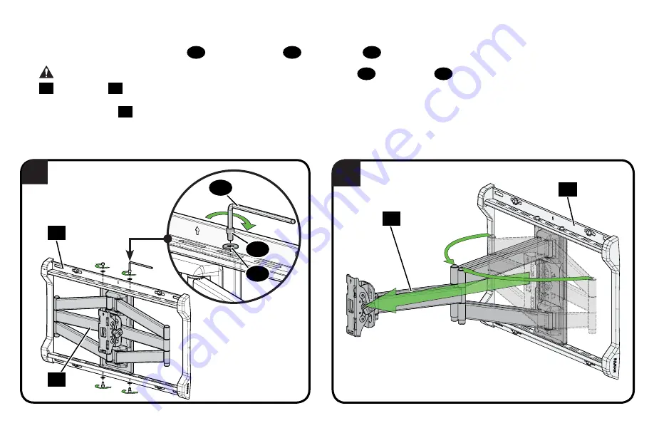
2.  Secure with four wall plate screws 

25

 and four washers 

26

 using hex key 

30

.

 CAUTION: 

Avoid potential personal injury or property damage! Screws 

25

 and washers 

26

 must be installed to secure arm assembly 

21

 to wall plate 

20

.

3.  Pull arm assembly 

24

 to full extension.

25

26

30

20

20

24

24

Summary of Contents for SLF9

Page 1: ...n for easy install video http san us 1043 SLF9 INSTRUCTION MANUAL We ll Make It Stress Free If you have any questions along the way just give us a call 1 888 333 1376 UK 0800 056 2853 We re ready to h...

Page 2: ...ll with wood studs Solid concrete or concrete block Call Customer Service 1 888 333 1376 UK 0800 056 2853 Perfect Perfect CAUTION Avoid potential personal injuries and property damage This product is...

Page 3: ...Mounting arm adjusts within the wall plate for optimal positioning Level adjustment creates a worry free installation Fully articulating arm with 3 pivot points creates optimal viewing positions Fit T...

Page 4: ...INTERFACE WALL PLATE 15 75 in 400mm 15 75 in 400mm 3 9 in 100mm 3 9 in 100mm 3 0 in 750 mm 2 95 in 750 mm 7 87 in 200 mm 7 87 in 200 mm 23 62 in 600mm 8 7 in 220 mm 17 3 in 440 mm 3 19 in 80 9 mm 3 46...

Page 5: ...ll parts are included and undamaged If any parts are missing or damaged do not return the damaged item to your dealer contact Customer Service Never use damaged parts NOTE Not all hardware included wi...

Page 6: ...cm 3 in 100 mm 10 cm 4 in 200 mm 20 cm 7 7 8 in 300 mm 30 cm 11 3 4 in 400 mm 40 cm 15 3 4 in 600 mm 60 cm 23 5 8 in Measure the width and height of your TV hole pattern in mm Record your measurements...

Page 7: ...00 mm 400 x 300 mm B C These smaller hole patterns only use TV bracket 01 Do not use the four TV bracket extenders 02 and eight screws 03 75 x 75 mm 100 x 100 mm 200 X 200 mm 02 03 2 95 75 3 94 100 7...

Page 8: ...et extenders 02 onto TV bracket 01 and secure using eight screws 03 in the corner holes indicated Assemble TV bracket extenders 02 onto TV bracket 01 and secure using eight screws 03 in the corner hol...

Page 9: ...the threaded inserts on the back of your TV to determine which screw diameter M4 M6 or M8 to use Too Short Too Long CAUTION Verify adequate thread engagement with the screw or screw spacer combination...

Page 10: ...juries and property damage DO NOT use a power screwdriver for this step IMPORTANT Ensure TV bracket is securely fastened before moving on to the next step 1 5 Attach TV Bracket TV Bracket Configuratio...

Page 11: ...pical viewing location position your TV so your eyes are level with the middle of the screen For most people this is between 40 and 60 101 cm and 152 cm above the floor For precise drilling locations...

Page 12: ...e is insta lled attac h the arm to the wall plate Next simp ly pick up your TV hang it on the arm and secu re it Cong ratul ation s You r e done We re here to help If you have quest ions at any point...

Page 13: ...ions scan the Heig htWi zard link below or cont act customer service GET STARTED WITH STEP 1 VIEWING HEIGHT RECOMMENDATION Grab the TV brac kets and line them up with the holes on the back of your TV...

Page 14: ...IN G TO ENJOY STEP 3 Once the wall plate is installe d attach the arm to the wall plate Next simply pick u p your TV hang it on the arm and secure it Congra tulatio ns You re done We r e here to help...

Page 15: ...six lag bolts 21 and six washers 22 two on the bottom four on top Tighten all lag bolts only until they are pulled firmly against the wall plate CAUTION Avoid potential personal injury or property dam...

Page 16: ...63 x 266 x 050 in 1 4 20 x 3 8 in 1 4 20 x 5 8 in 3 16 in 563 x 266 x 050 in 1 4 20 x 3 8 in 1 4 20 x 5 8 in 3 16 in Parts and Hardware for STEP 3 1 Hardware for STEP 3 2 Parts for STEP 3 3 Parts and...

Page 17: ...channel C then rotating the bottom toward the wall CAUTION Avoid potential injury or property damage For concrete applications the base of the arm 24 must remain centered in the wall plate 20 NOTE Whe...

Page 18: ...5 and four washers 26 using hex key 30 CAUTION Avoid potential personal injury or property damage Screws 25 and washers 26 must be installed to secure arm assembly 21 to wall plate 20 3 Pull arm assem...

Page 19: ...onto the arm assembly 24 by first hooking the hang tab H then resting the TV into place 2 Lock the TV to the arm assembly 24 with locking screw 27 using hex key 30 CAUTION Avoid potential personal in...

Page 20: ...cable covers 28 and 29 then install cable covers 28 and 29 onto arms 24 IMPORTANT Fully extend arm 24 to ensure you have enough slack in the cables during operation 3 3 Manage Cables 28 29 29 28 SIDE...

Page 21: ...into the channels of the wall plate 20 NOTE Hex key 30 can be stored behind the upper cover plate for future use Before installing the covers use the hex key to make any necessary adjustments as shown...

Page 22: ...in wrench not supplied to hold the nut in place NOTE Once your TV is in place tighten the top tension bolts B to prevent unwanted movement and replace end cap TILT ADJUSTMENT Your TV should adjust eas...

Page 23: ...lace the cover plates 31 see STEP 3 4 5 Hang the TV onto the arm assembly 24 following STEP 3 2 TV LATERAL SHIFT LEVEL ADJUSTMENT 30 CAUTION Avoid potential injury or property damage DO NOT adjust the...

Page 24: ...screws 25 and washers 26 from wall plate 20 using hex key 30 4 Swing the lower portion of arm assembly 24 out and lift the arm assembly out of wall plate 20 1 Disconnect all cables from your TV 2 Remo...

Page 25: ...upplied Spacers a b FLAT BACK ROUND BACK CABLES a Use your TV supplied spacer for flat back TVs AND you want your TV closer to the wall b Use your TV supplied spacer and spacer 14 for Round irregular...

Page 26: ...Tiene todas las herramientas necesarias 1 2 3 4 De qu est hecha su pared No est seguro Hormig n s lido o bloques de cemento 68 kg 150 lbs Listo para comenzar 13 mm 1 2 Tabiques de yeso con montantes...

Page 27: ...ermanecer en la posici n central en la placa mural Las perillas de ajuste permiten el ajuste manual o limitar el movimiento Las cubiertas de cable sujetan los cables a lo largo del brazo para un aspec...

Page 28: ...laca de sujeci n Coloque la configuraci n del soporte de su televisor A B C D E o F en su televisor asegur ndose de que el soporte est centrado y nivelado sobre el patr n de orificios de su televisor...

Page 29: ...onar la ubicaci n de su soporte mural 2 Realice los orificios gu a en el hormig n s lido Nunca perfore el cemento que une los bloques IMPORTANTE Los orificios gu a deben realizarse con una mecha de 10...

Page 30: ...mural 20 para un posicionamiento ptimo del televisor 2 Fijeconcuatrotornillosparaplacamural 22 ycuatroarandelas 26 usandounallavehexagonal 30 PRECAUCI N Eviteposibleslesionesf sicasyda osmateriales Lo...

Page 31: ...tornillos de nivelaci n L DESPLAZAMIENTO LATERAL DEL TELEVISOR PRECAUCI N Eviteelriesgodelesionesyda osmateriales Paraaplicacionesdelhormig n brazo 24 debepermanecerenlaposici ncentralenlaplacamural...

Page 32: ...im We will discuss the problem with you and once we confirm the product is under warranty we will ship replacement parts at no cost to you within 72 hours This Limited Warranty does not cover the cost...

Reviews: