background image

18

¡ELEMENTO PESADO! Es posible que necesite ayuda 

en este paso.

IMPORTANTE:

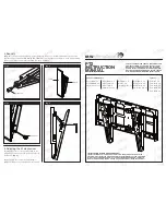
 Oirá un clic cuando la placa de sujeción del 

televisor esté bien sujeta a la placa mural.

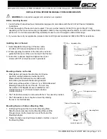
PASO 3 Instalar el televisor en la pared

Ajustes

Ver página 12

Ver página 13

AJUSTE DE LA INCLINACIÓN: 

Afloje la perilla  

que se encuentra en la placa de sujeción del 

televisor a fin de ajustar la inclinación de su 

televisor. Ajuste la perilla cuando su televisor 

tenga la inclinación deseada.

RETIRAR EL TELEVISOR: 

Jale hacia 

abajo de las correas, levante el 

televisor y retírelo de la placa mural.

AJUSTE DE LA NIVELACIÓN: 

Si es necesario, 

ajuste uno de los tornillos de la parte superior  

de la placa de sujeción del televisor para nivelar  

el televisor.

ESPAÑOL

Summary of Contents for HMT1

Page 1: ...xperts are standing by to help Call us at 888 384 1115 Or chat at SANUS com chatSH Get it right the first time HeightFinder shows you where to drill Check it out at SANUS com 2933 Want to watch a video that shows how easy this DIY project will be Watch it now at SANUS com 2939 WE RE HERE TO HELP ...

Page 2: ...r wall made of Ready to begin Does yourTV including accessories weigh more than 80 lbs 36 3 kg CAUTION DO NOT install into drywall alone Unsure Drywall with wood studs Solid concrete or concrete block Call Customer Service 888 384 1115 Perfect CAUTION Avoid potential personal injuries and property damage This product is designed for use in wood stud solid concrete and concrete block walls DO NOT i...

Page 3: ... 7mm 2 93in 74 4mm 3 91in 99 4mm 0 33in 8 4mm 17 78in 451 6mm 16 93in 430mm 0 38in 9 7mm OFFSET 7 87in 200mm LATERAL SHIFT AT 200 VESA 0 35in 8 8mm 6 50in 165 2mm 2 04in 51 8mm LEVEL ADJUST SCREW 5deg TIL UP 10deg TILT DOWN TV INTERFACE WALL PLATE FRONT VIEW LATERAL SHIFT 3 D SIDE VIEW TILT SIDE VIEW FULLY ASSEMBLED MOUNT ...

Page 4: ...eturn the damaged item to your dealer contact Customer Service Never use damaged parts NOTE Not all hardware included will be used STEP 1 Parts and Hardware M6 x 12mm M6 x 35mm M6 x 20mm M4 x 12mm M4 x 35mm M8 x 16mm M8 x 35mm M8 x 25mm M8 x 50mm TV Bracket TV Screws qty 4 each Only one size fits your TV Washers Spacer If necessary 03 02 01 M6 M8 M4 M4 M6 M8 22 mm M4 M6 M8 2 5 mm M4 M6 M8 qty 1 04...

Page 5: ...0 x 075 in 5 16 in 5 16 x 2 in Contact Customer Service at 888 384 1115 to inquire about the CMK1 Concrete Installation Kit Fischer UX 10 x 60R Anchor M4 M5 M6 M8 M8 x 35mm M6 x 35mm 5 16 x 2 3 4 in 5 16 in M8 x 50mm M8 x 40mm 2 5mm 5mm 22mm Lag Bolt Washer 09 5 16 x 2 in 695 x 350 x 075 in 5 16 x 2 in 08 5 16 in qty 1 06 qty 1 07 qty 2 qty 2 C1 qty 3 C2 qty 3 C3 qty 3 ...

Page 6: ...e spacers and longer screws b to accommodate Round irregular back TVs TVs with inset mounting holes Extra space needed for cables Too Short Too Long CAUTION Verify adequate thread engagement with the screw or screw spacer combination Too short will not hold the TV Too long will damage the TV Correct M4 M6 M8 Only one size fits your TV If your TV included inset spacers or wall mount adapters use th...

Page 7: ...s 04 and 05 are level on the back of the TV Standard configurations are shown For special applications or if you are unsure about your hardware selection contact Customer Service a Flat Back b Round Back Extra Space 03 02 02 01 01 04 05 Spacer Options ...

Page 8: ... stud size nominal 2 x 4 in 51 x 102 mm actual 11 2 x 31 2 in 38 x 89 mm 1 Locate your stud Verify and mark the center of the stud by finding the stud edges using an awl a thin nail or an edge to edge stud finder 2 Position the wall plate template 06 at your desired height and line up the holes with your stud center line Level the template and tape in place 2 1 Max 5 8 in 16 mm 06 ...

Page 9: ... wall plate 07 using two lag bolts 08 and two washers 09 Tighten the lag bolts only until they are pulled firmly against the wall plate CAUTION Avoid potential personal injury or property damage Both lag bolts 08 MUST BE firmly tightened to prevent unwanted movement of the wall plate 07 Ensure the wall plate is securely fastened to the wall before continuing on to the next step 4 08 09 3 3 in 75 m...

Page 10: ... injuries and property damage Mount the wall plate 07 directly onto the concrete surface Minimum solid concrete thickness 8 in 203 mm Minimum concrete block size 8 x 8 x 16 in 203 x 203 x 406 mm Minimum horizontal space between the top two fasteners 4 3 4 in 120 6 mm 1 Position the wall plate template 06 on the wall at your desired height Level the wall plate template and mark the hole locations 2...

Page 11: ...g bolts and washers from the Concrete Installation Kit Tighten the lag bolts only until the washers are pulled firmly against the wall plate CAUTION Avoid potential personal injury or property damage All three 3 lag bolts C1 MUST BE firmly tightened to prevent unwanted movement of the wall plate 07 Ensure the wall plate is securely fastened to the wall before continuing on to the next step Contact...

Page 12: ...3 Attach TV to Wall Plate HEAVY You may need assistance with this step IMPORTANT You will hear an audible click when the TV bracket is securely fastened to the wall plate 07 07 07 07 04 05 04 05 04 05 04 05 2 1 ...

Page 13: ...ghten one of the screws on the top of the TV bracket to level the TV TILT REMOVING THE TV LEVEL Your TV should adjust easily when moved then stay in place If your TV is too loose or too tight adjust the tilt tension knob by hand NOTE Once your TV is in place tighten the tilt tension knob to prevent unwanted movement ...

Page 14: ...amientas necesarias 1 2 3 4 De qué está hecha su pared No está seguro Hormigón sólido o bloques de cemento Listo para comenzar 13 mm 1 2 Tabiques de yeso con montantes de madera Llame al 888 384 1115 Perfecto El Kit de instalación en hormigón no está incluido Destornillador Cinta métrica Broca Broca Taladro eléctrico Martillo Llave de tubo PRECAUCIÓN Evite posibles lesiones personales y daños mate...

Page 15: ...SO 1 Colocar la placa de sujeción en el televisor Dimensiones Ver página 3 Ver página 4 Ver página 6 1 1 Seleccione el diámetro de los tornillos para el televisor 1 2 Seleccione la longitud de los tornillos para el televisor 1 3 Fije los soportes para televisor Enrosque manualmente los tornillos en los encastres roscados del dorso del televisor a fin de determinar qué diámetro de tornillos M4 M6 o...

Page 16: ... de placa mural 06 a la altura deseada y alinee los orificios con la línea central de los montantes Nivele la plantilla y fíjela con cinta adhesiva en el lugar 3 Realice los orificios guía con una mecha de 5 5 mm 7 32 de diámetro Retire la plantilla de la placa mural 06 IMPORTANTE Asegúrese de perforar el centro del montante IMPORTANTE Los orificios guía deben realizarse hasta una profundidad de 7...

Page 17: ... Realice los orificios guía con una mecha para mampostería de 10 mm 3 8 de diámetro IMPORTANTE Los orificios guía deben realizarse hasta una profundidad de 75 mm 3 Nunca perfore el cemento que une los bloques 3 Retire la plantilla de la placa mural 06 e introduzca tres anclajes C3 Fischer UX 10 x 60R incluidos en el Kit de instalación en hormigón CMK1 PRECAUCIÓN Cerciórese de que los anclajes qued...

Page 18: ...NACIÓN Afloje la perilla que se encuentra en la placa de sujeción del televisor a fin de ajustar la inclinación de su televisor Ajuste la perilla cuando su televisor tenga la inclinación deseada RETIRAR EL TELEVISOR Jale hacia abajo de las correas levante el televisor y retírelo de la placa mural AJUSTE DE LA NIVELACIÓN Si es necesario ajuste uno de los tornillos de la parte superior de la placa d...

Page 19: ...19 ESPAÑOL ...

Page 20: ...e contingency in connection with the installation or use of this product The information contained in this document is subject to change without notice or obligation of any kind Legrand makes no representation of warranty expressed or implied regarding the information contained herein Legrand assumes no responsibility for accuracy completeness or sufficiency of the information contained in this do...

Reviews: