


<AR coating option>
Item
Units
Ordering code number
-01
-02
-03
-04
-12
-
AR coat range
450-550
750-850
1000-1100
1500-1600
400-800
nm
AR coat reflectance
4)
<1.5
%
4)Angle of incidence = 0 degree
Parameter
-14
450-550 / 1500-1600
<0.5
<0.6
<Optical Characteristics>
Min
Max
Units
Notes
450
1600
nm
(Refer to appended table about AR coating option)
2
p
-
rad.
-
%
Depending on specified wavelength range
%
-
m
m
-
mm
Active area
pixels
-
ms
Depending on LCOS phase pattern
Hz
-
rad.
-
bit
-
W/cm
2
1550nm CW, 2.0mm beam diameter
15
35
°C
No condensation
0
40
°C
No condensation
1) Specification on the defect pixels are no object.
2) Tr, Tf : Response time between 10% and 90% levels at 25degC typ.
3) The value is not guaranteed.
<Electrical and Mechanical characteristics>
Min
Max
Units
Notes
-
-
Hz
-
100
240
VAC
-
mm
-
All-in-one model
kg
-
Separate model
kg
-
-
Width x Depth x Height
117.6 x 117.6 x 33.7
Weight
0.39
0.48
Control software
GUI for windows
Item
Interface
Digital Video Interface (DVI-D),
USB3.0 (typeB)
DVI frame rate
60
Input voltage to AC adapter
Gray level
10 (1024)
Optical power handling
3)
Typ. 10
Operating temperature
Storage temperature
Response speed
2)
Typ. 300
LCOS drive frequency
1200
Relative phase fluctuation
Typ. <0.001
p
Pixel size / pitch
7.8 / 8.0
Panel size
(H)15.36 x (V)9.6
Addressable Active matrix
1)
(H)1920 x (V)1200
Item
Wavelength Range
Phase shift
Panel reflectivity
Typ. >80
Aperture ratio
95
9
Display specifications
2. Display specifications
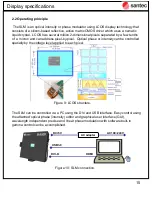
2.1 Parameters
Table 1: Specifications
.
Summary of Contents for LCOS-SLM
Page 6: ...6 Introduction Figure 2 LCOS unit handling...
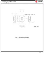
Page 12: ...12 Display specifications Figure 6 Dimensions All in one model Unit mm...
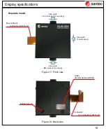
Page 13: ...13 Display specifications Figure 7 Dimensions Separate model Unit mm...
Page 14: ...14 Display specifications Figure 8 Dimensions LCOS unit Unit mm...
Page 23: ...23 Figure 24 Side view Display specifications 6 M2 6 screw hole for mounting...
Page 36: ...36 2 Please select Browse my computer for driver software Software package...
Page 37: ...37 3 Select adequate OS folder on attached CD contents Software package...
Page 38: ...38 4 Installation of USB driver Software package...
Page 51: ...51 4 2 2 8 Set CSV pattern The preview of specified display data is displayed Software package...
Page 70: ...70 4 3 3 Effective area of BMP image Software package...


