background image


- 2 - 


Dismantling for installation 


• The hand dryer is supplied with the metallic cover coupled to the base in a 

unscrewed stated.  


• The cover should be extracted taking into account its upper rib placed in its    

fitting on the base.  


• The cover must be removed obliquely until the upper rib has been extracted. 


Take care to avoid: 
 
     - Damaging the internal parts (mainly electronic components) 
 
     - Damaging the cover. It is recommended placing it on a flat 
       surface facing upwards and on a cloth. 


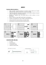
Mounting 


The assembly should be preferably  
prepared for rear ducting. 


• Drill holes of 5/16” (8 mm) in the 

wall, using the template supplied.  

 
Clean the holes of the resulting dust 

and insert the plugs. 

 
• Pass the power cables from the wall 

through the 7/8” (22 mm) hole 
situated beneath the connection 
board of the appliance. 

 
• Screw the base of the appliance 

tightly to the wall ensuring the 4 
silent-blocks are correctly positioned. 

 
• Enter the power cables and earth 

wire into the inside space containing 
the terminal strip, passing them 
through the entry hole. 


ENGLISH 


INSTALLATION 


Summary of Contents for M02A-UL

Page 1: ...AND DRYERS SÉCHE MAINS SECADOR DE MANOS M02A UL M02AC UL M02ACS UL M03A UL M03AC UL M03ACS UL INSTALLATION AND OPERATING MANUAL MANUEL D INSTALLATION ET D UTILISATION MANUAL DE INSTALACIÓN Y UTILIZACIÓN ...

Page 2: ...ng it on a flat surface facing upwards and on a cloth Mounting The assembly should be preferably prepared for rear ducting Drill holes of 5 16 8 mm in the wall using the template supplied Clean the holes of the resulting dust and insert the plugs Pass the power cables from the wall through the 7 8 22 mm hole situated beneath the connection board of the appliance Screw the base of the appliance tig...

Page 3: ...ether The detection of the hands and the later start up of the appliance is based on the emission reflection reception of an IR light beam that comes from the sensors positioned close to the exit outlet area On removing the hands the appliance stops in 2 3 seconds The appliance includes a protection system against continuous improper use it stops after 120 seconds of continuous use M02A UL M02AC U...

Page 4: ...dust covering on its surface Open the volute removing the safety screw and folding the closure clips and clean the turbine and heating element of dust Close the volute again putting in the closure clips and tightening the safety screw Clean the dust from the perimeter of the base especially the upper section Assemble the cover place the lower screws and connect the dryer once again Start up the ma...

Page 5: ...atin finish stainless steel cover 1 RC82020 Bright finish stainless steel cover 1 RC82030 Fan wheel 2 RC82777 Motor 3 RC82748UL Heating element 4 RC82770UL RC82720UL Electronic circuit set 5 RC82600UL RC82610UL IR sensor circuit 6 RC82601UL Main electronic card 7 RC82602UL Coal brushes set 8 RC95750 AMT WIRING DIAGRAM BREAKDOWN LIST OF BASIC PARTS ...

Page 6: ... composants électroniques De ne pas endommager la carcasse Il est conseillé de la poser à l endroit sur une surface plane et au dessus d un chiffon Montage L assemblage devra de préférence être prévu pour des conduits arrière Percer des trous de 5 16 8 mm de diamètre dans le mur à l aide du modèle fourni Bien enlever la poussière des trous et y insérer les chevilles Faire passer les câbles d alime...

Page 7: ...de la sortie d air et frotter les mains l une contre l autre La détection des mains et le démarrage consécutif de l appareil sont basés sur l émission la réflexion et la réception d un faisceau de lumière infra rouge qui est provient par les capteurs placés à proximité de l orifice de sortie Après le retrait des mains l appareil s arrête au bout de 2 à 3 secondes L appareil est doté d un système d...

Page 8: ...sière accumulée sur sa surface Ouvrir la volute en retirant la vis de blocage et en repliant les pinces de fermeture et nettoyer la poussière de la turbine et de la résistance Refermer la volute en remettant en place les pinces de fermeture et serrer la vis de blocage Enlever la poussière du périmètre de la base en particulier sur la partie supérieure Remonter la carcasse placer les vis du bas et ...

Page 9: ...inition satinée 1 RC82020 Carcasse en acier inoxydable finition brillante 1 RC82030 Tourniquet de ventilateur 2 RC82777 Moteur 3 RC82748UL Résistance 4 RC82770UL RC82720UL Ensemble circuit électronique 5 RC82600UL RC82610UL Circuit du capteur IR 6 RC82601UL Carte électronique principale 7 RC82602UL Ensemble balais de carbone 8 RC95750 AMT SCHEMA ELECTRIQUE LISTE DES PRINCIPALES PIÈCES ...

Page 10: ... mm en la pared utilizando la plantilla suministrada Limpiar los agujeros del polvo resultante e insertar los tacos Pasar los cables de alimentación procedentes de la pared a través del agujero de 7 8 22 mm situado bajo la regleta de conexión del aparato Atornillar con firmeza la base del aparato a la pared asegurando que los 4 silent bloks estén correctamente alojados Introducir los cables de ali...

Page 11: ...que están próximos a la salida de aire Una vez retiradas las manos la máquina para en 2 3 segundos El aparato está dotado de un sistema de protección contra un uso inadecuado la máquina para después de 120 segundos de uso contínuo Modelos M02A UL M02AC UL y M02ACS UL Estos modelos de secadoras de manos tienen un sistema automático de control de la temperatura Suministra en cada momento a través de...

Page 12: ...llo de seguridad y doblando los clips de cierre Limpiar de polvo la turbina y el elemento calefactor Volver a cerrar la voluta entrando nuevamente los clips de cierre y atornillando el tornillo de seguridad Limpiar de polvo el perímetro de la base especialmente la franja superior Montar la carcasa colocar los tornillos inferiores y conectar nuevamente Poner en marcha la máquina repetidas veces con...

Page 13: ...casa de acero inoxidable acabado satinado 1 RC82020 Carcasa de acero inoxidable acabado brillante 1 RC82030 Turbina 2 RC82777 Motor 3 RC82748UL Resistencia 4 RC82770UL RC82720UL Circuito electrónico Cable 5 RC82600UL RC82610UL Circuito placa electrónica LEDs 6 RC82601UL Circuito electrónico 7 RC82602UL Escobillas 8 RC95750 AMT DESPIECE BÁSICO ESQUEMA ELÈCTRICO ...

Page 14: ...s Tiempo SIZE DIMENSIONS DIMENSIONES Height Hauteur Alto 12 8 325 mm Width Largeur Ancho 10 82 275 mm Depth Profondeur Profundo 6 5 164 mm CASING CAPOT CARCASA Type Type Tipo Steel Acier Acero Stainless steel AISI 304 Acier inoxydable AISI 304 Acero inoxidable AISI 304 Acero Steel Acier Stahl Stainless steel AISI 304 Acier inoxydable AISI 304 Acero inoxidable AISI 304 Thickness Épaisseur Espesor 5...

Page 15: ...he wall to mark location of four mounting screw holes Drill four holes Fig 1 Ø8 5 16 diameter and 45mm 1 depth Take off the residual dust from the holes Insert nylon plugs provided into four holes Fig 2 3 Place base plate on wall Fig 4 Fix the base plate firmly on the wall Fig 5 6 MOUNTING ITEMS PROVIDED 4 screw 4 Plug 1 Mounting template 1 Instruction manual NYLON PLUG D8 ...

Page 16: ...marquer l emplacement des quatre trous pour les vis Percer quatre trous Figure 1 de 8 mm 5 16 de diamètre et de 45 mm 1 3 4 de profondeur Enlever la poussière des trous Insérer les chevilles en nylon fournies dans les quatre trous Figures 2 3 Placer la plaque de base sur la paroi Figure 4 Fixer solidement la plaque de base sur la paroi Figures 5 6 ÉLÉMENTS DE MONTAGE FOURNIS 4 vis 4 chevilles 1 mo...

Page 17: ...os de los tornillos de fijación Realizar los 4 agujeros Fig 1 de diámetro Ø8 mm 5 16 y 45mm 1 de profundidad Eliminar el polvo que haya podido quedar dentro de los agujeros Insertar en los agujeros los 4 tacos de Nylon suministrados Fig 2 3 Colocar la base del secador de manos en la pared Fig 4 Fijar dicha base a la pared firmemente a la pared Fig 5 6 MOUNTING ITEMS PROVIDED 4 Tornillos 4 Tacos de...

Page 18: ... 18 ...

Page 19: ... 19 ...

Page 20: ...2 Tel 001 305 424 24 33 Fax 001 305 424 24 35 Toll free 1 877 222 91 25 info saniflowcorp com www saniflowcorp com SPAIN ESPAÑA ESPAGNE MEDICLINICS S A Industria 54 E 08025 BARCELONA Tel 34 93 446 47 00 Fax 34 93 348 10 39 info mediclinics com www mediclinics com 13 04 15 COD 82917UL ANON ...

Reviews: