KBox A-150-SKL - User Guide Rev. 1.1
// 24
Internal Components
4.5.
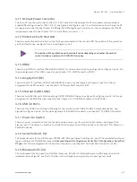
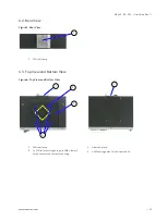
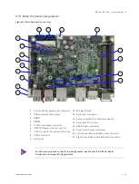
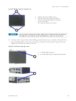
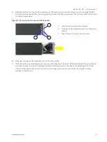
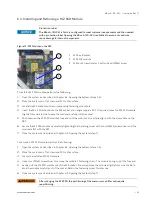
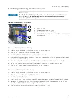
Figure 9: Internal Components
1
Main chassis
2
2.5” HDD/SSD drive bay
3
SATA connector
4
2x Screw holes for2x bottom head (M3x5) screws
5
3x Main chassis screws holes for 3x flathead
(M2 5x6) screws.
(Corresponding to front panel screw holes, pos.10)
6
3.5” SBC
7
1x mPCIe slot with card
8
1x M.2 socket with module
9
Lithium battery
10
3x Front panel screw holes for 3x flathead
(M2 5x6) screws
(Corresponding to main chassis screw holes, pos. 5)
11
Front panel
12
2x Wi-Fi antenna cables
13
System memory (DIMM1, DIMM2)
4
1
2
3
5
6
13
11
9
10
12
8
7


