S&T CAREU U1 Lite(WR) User Manual Download Page 11

CAREU U1 Lite(WR) Vehicle Tracker User 
Guide


Chapter 3


7


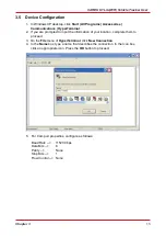
3.4    USB Device Driver Installation


The  CAREU  U1  Lite(WR)  communicates  with  your  host  computer  by  either  RS-232  or  USB 
interface. In some newer editions of Windows XP, the CAREU U1 Lite(WR) device can be installed 
as  a  "virtual  COM  port"  device  whereby  the  CAREU  U1  Lite(WR)  would  automatically  access 
Windows  XP's  inbox  USB  drivers.  While  in  some  other  earlier  editions  of  Windows  XP,  you 
would  need  to  manually  install the USB driver for the CAREU U1 Lite(WR) device. In the following 
content of this section, you will be guided to how the installation can be done in both cases. 


To install the device driver for the CAREU U1 Lite(WR), connect the CAREU U1 Lite(WR) device 
to your system with an USB cable as mentioned in Mini USB Cable Connection on section 3.1. As 
soon  as  the  connection  is  made  between  the  CAREU  U1  Lite(WR)  and  your  computer,  a  balloon 
appears above the notification area saying an USB device is found. 


Click on this balloon to start the 

[Found New Hardware] 

wizard. 


Select 

No, not this time

. Press the 

Next 

button to proceed. 


Summary of Contents for CAREU U1 Lite(WR)

Page 1: ...CAREU U1 Lite WR Vehicle Tracker User Guide Version 1 0 Reference No AVL CU U1L 00 1210UEN Date March 30 2012 SYSTEMS TECHNOLOGY CORP...

Page 2: ...rmation in this document is subject to change without notice at any time Disclaimer The information specification images and photos in this user guide are subject to change without notice and without...

Page 3: ...Chapter 2 Taking a Tour of CAREU U1 Lite WR 3 2 1 Dimensions 3 2 2 Front View 3 3 2 Pin Assignment 5 3 3 LED Indicator 6 3 4 USB Device Driver Installation 7 3 5 Device Configuration 13 3 6 Communicat...

Page 4: ......

Page 5: ...device configuration only please see the CAREU U1 Lite WR Protocol Document for the advanced information 1 3 About CAREU U1 Lite WR The CAREU U1 Lite WR vehicle tracker transmits the wireless signals...

Page 6: ...unication status and it also provides better power management coexistence of GPRS and SMS modes 1 4 Hardware Architecture As hardware is concerned the CAREU U1 Lite WR is comprised of a micro controll...

Page 7: ...ll guide you to the major connectors of the CAREU U1 Lite WR vehicle tracker 2 1 Dimensions Dimensions L x W x H 72mm x 90mm x 33mm 72mm 33mm 90mm 2 2 Front View No Name Description 1 PWR I O Power Co...

Page 8: ...a Connection Connect the GPS antenna to the SMA connector jack on the front side of the device circled as the illustration below by completely screwing the GPS antenna s plug connector It is recommend...

Page 9: ...nition Ignition ACC Input I DC Vin 30 7V Active high 4 Output1 Open Collector O Imax 300mA 5 Input 1 Negative Trigger Input 1 I DC VIN 6V 0V Low Active 6 Output 2 Open Collector Output 2 O Imax 300mA...

Page 10: ...de GPS Status GPS LED Power Off N A Off Low Power N A Off Full Power Acquiring Flash Red 5 Times Second Full Power Tracking Solid Red 2 GSM LED Indicator Power Mode GSM GPRS Status GSM LED Power Off N...

Page 11: ...ld need to manually install the USB driver for the CAREU U1 Lite WR device In the following content of this section you will be guided to how the installation can be done in both cases To install the...

Page 12: ...r 3 1 Automatic Installation If the wizard prompts to help you install the software for STMicroelectronics Virtual COM Port Select Install the software automatically Recommended Press the Next button...

Page 13: ...ehicle Tracker User Guide Chapter 3 9 The installation completes In Device Manager the CAREU U1 Lite WR device is included under Ports COM LPT as STMicroelectronics Virtual COM Port COM port number is...

Page 14: ...all the driver Select Install from a list or specific location Advanced Press the Next button to proceed Select Search for the best driver in these locations Check Include this location in the search...

Page 15: ...CAREU U1 Lite WR Vehicle Tracker User Guide Chapter 3 11 Press the Next button to proceed The wizard proceeds to install the driver...

Page 16: ...1 Lite WR Vehicle Tracker User Guide 1 2 Chapter 3 The installation completes In Device Manager the CAREU U1 Lite WR device is included under Ports COM LPT as S T Tracker COM port number is displayed...

Page 17: ...rompted to input the information of your location complete them to proceed 3 On the File menu of HyperTerminal click New Connection 4 In the Name box type a name that describes the connection In the I...

Page 18: ...just set up click File Properties Select the Connect To tab From the Connect using drop down list select the correct com port by checking it up at Windows XP s DeviceManager as previously mentioned on...

Page 19: ...Guide Chapter 3 15 7 In the File menu click Properties Click the Settings tab Press the ASCII Setup button 8 In the ASCII Sending group box Select both Send line ends with line feeds and Echo typed c...

Page 20: ...e device startup message will be displayed 10 In HyperTerminal window type in the command AT VERSION and press the Enter key The hardware and firmware version will show As long as your HyperTerminal w...

Page 21: ...SMSDST 886123456789 OK Then you can try to use cellular phone or SMS gateway to send a SMS message to the CAREU U1 Lite WR device Send a SMS message AT MODID Device will response MODID 101000001 OK Th...

Page 22: ...T PDSR 1 30 0 0 2 0 0 1 1 Tracking through GPRS by time interval 30 seconds OK For simple testing GPRS run the TCP Server U Series software which is provided by S T It is simple server software that c...

Page 23: ...Such firmware loader runs on Windows based systems To upgrade the firmware follow the procedure below 1 Connect the device to your PC with the USB cable 2 Connect the device to power 3 Power on the d...

Page 24: ......

Page 25: ...GPRS Mode Multi slot Class 10 GPRS Coding Scheme CS1 CS2 CS3 and CS4 GSM Antenna External SIM Interface SIM Card 1 8V 2 9V Supported GPS Functionality Receiver 50 Channels Sensitivity Tracking 160dBm...

Page 26: ...Negative Trigger 1 Analog Input 1 0 30V 12 Bits Output Ports Negative Triggers 2 300mA Electrical Power Source DC 8V to 30V Power Consumption 72mA 12V Operating Mode 8mA 12V Standby Mode 6mA 12V Deep...

Page 27: ...ng the equipment off and on the user is encouraged to try to correct the interference by one or more of the following measures Reorient or relocate the receiving antenna Increase the separation betwee...

Page 28: ...te the most advanced and comprehensive GPS tracking products for the customers and has built a global service network to provide non stop services and support With the well established marketing netwo...

Reviews: